


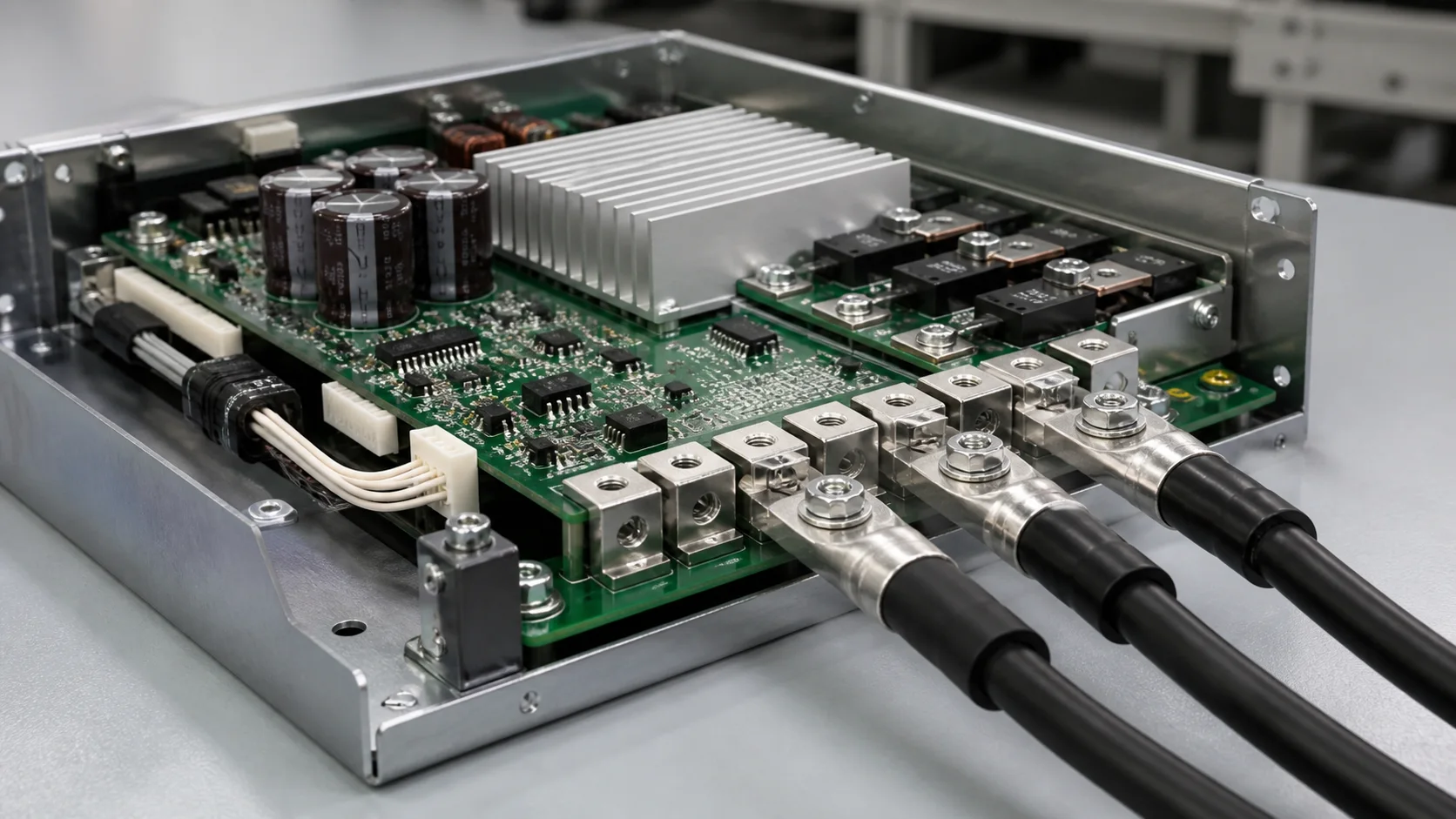
Quick answer: Select a servo-controller welding terminal by combining the three-phase current path with cable loads. Legs, solder and PCB copper conduct current; lug and bolt make the external connection; a bracket or housing carries cable bending and vibration. Validate phase-to-phase temperature, contact resistance, joint strength, torque retention and post-vibration drop.
Questions answered on this page
- Why use PCB welding terminals for servo three-phase output?
- How can cable bending be kept away from the solder joint?
- How can the three phases stay electrically balanced?
- How should hole, pad and solder process be matched?
- What should be checked after vibration and service?
Application context
A servo controller routes U/V/W inverter output through PCB copper and welding terminals to the motor cable. Robot joints and control cabinets add motion, fan vibration and service cycles. Hongchuan supplies PCB welding terminals and high-current PCB hardware.
Selection boundaries
| Boundary | Review | Risk |
|---|---|---|
| Current | Continuous, peak, PWM ripple and drop | Phase imbalance |
| Solder | Leg, hole, pad, fill and process | Resistance or strength loss |
| Mechanical | Cable direction, support, torque and board bend | Fatigue or crack |
| Insulation | Phase spacing and housing tolerance | Discharge or interference |
| Service | Tool access and repeated fastening | Repair damage |
Phase balance and cable support
Match section, path length, pad, hole and fastening conditions across U/V/W. Measure each phase body, solder, copper exit and lug drop under rated load and correlate with phase current and temperature. A cool body can hide a hot joint or pad exit. See PCB terminal temperature testing.
Use a clamp, bracket or housing stop for thick dynamic motor cables. Bolt torque that is too high bends the board; too low increases micro-motion and resistance. Welding strength cannot replace external support. See terminal hole and pad design.
Vibration and temperature validation
Test in the real mounting orientation. Before and after vibration and shock, repeat resistance, phase drop and temperature measurements and inspect cracks, board deformation, loosened bolts and cable support. Thermal cycling should include the real motor-output load profile rather than a short room-temperature run.
FAQ
Must all three terminals be identical?
Keep structure, path and process consistent where possible. Measure phase current, segmented drop and temperature when space forces differences.
Can more solder joints replace a cable bracket?
No. The housing or support should carry external mechanical load.
What inputs are needed for samples?
Provide phase current, PWM condition, board, copper, hole, lug, bolt and mounting orientation. See the high-current PCB hardware selection guide.