


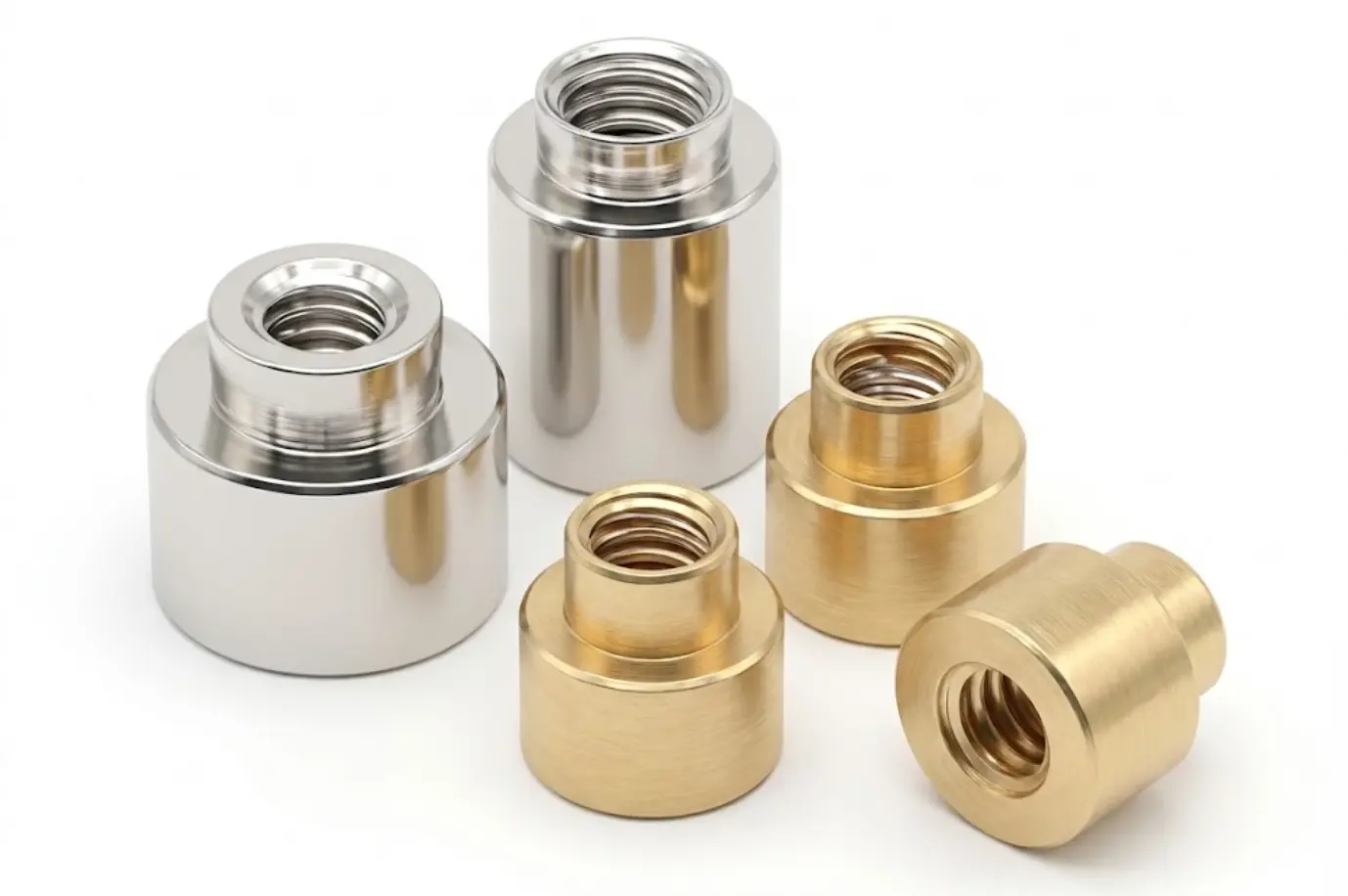
Start with the thread or catalog code, outside diameter and height. Open a model for its specifications and available drawing, then compare the PCB pad reference. Confirm screw engagement, pickup surface and reflow conditions for the selected part.
| Model | Thread / catalog code | Outside diameter / height | Packaging | Specifications |
|---|---|---|---|---|
| HCSMT-M40-D974-L110-BN | M4 | Ø 9.74 / 11 | Tape & reel | Model details Drawing PDF |
| HCSMT-K30-D556-L30-BNR | K3 | Ø 5.56 / 3 | Tape & reel | Model details Drawing PDF |
| HCSMT-M20-D556-L10-BNR | M2 | Ø 5.56 / 1 | Tape & reel | Model details Drawing PDF |
| HCSMT-M20-D556-L80-BNR | M2 | Ø 5.56 / 8 | Tape & reel | Model details Drawing PDF |
| HCSMT-M20-D556-L90-BNR | M2 | Ø 5.56 / 9 | Tape & reel | Model details Drawing PDF |
| HCSMT-M20-D556-L60-BNR | M2 | Ø 5.56 / 6 | Tape & reel | Model details Drawing PDF |
For samples or a quote, include the model or thread, height, PCB pad drawing and quantity. Confirm thread pitch, screw engagement and assembly torque against the selected drawing and validation conditions.


Detailed product parameters and performance indicators
Why Choose HCSMT Series SMT Nuts
Standardized design reduces development time and unit cost. SMT automated production significantly reduces manual labor.
EIA standard tape reel packaging, compatible with high-speed P&P machines. Standardized nozzle design for easy operation.
Compact size enables safety stock for fast delivery. Gold or lead-free tin plating improves reflow soldering.
Standard SMT nut datasheet and PCB pad design reference


Confirm dimensions against the model drawing. Catalog current is a reference; verify PCB pads, solder joint strength and temperature rise.
| Thread | Pitch | Type | Code | Length Code "H" ±0.13 (mm) | Min.Sheet | A Max | C Max | L Ref | Hole | ØD | Min.Pad | Reference(A) | Torque(Kgf) | |||||||||||||||||||
|---|---|---|---|---|---|---|---|---|---|---|---|---|---|---|---|---|---|---|---|---|---|---|---|---|---|---|---|---|---|---|---|---|
| 0.5 | 1 | 1.5 | 2 | 2.5 | 3 | 3.5 | 4 | 4.5 | 5 | 5.5 | 6 | 6.5 | 7 | 8 | 9 | 10 | 11 | 12 | 13 | |||||||||||||
| M1x0.25 | - | HC-SMT | M1 | 0.5 | 0.48 | 2.41 | 3.66 | 3.18 | 2.5 | 4.19 | 15 | 0.3 | ||||||||||||||||||||
| M1.2x0.25 | - | HC-SMT | M1.2 | 0.5 | 0.48 | 2.41 | 3.66 | 3.18 | 2.5 | 4.19 | 15 | 0.6 | ||||||||||||||||||||
| M1.4x0.3 | - | HC-SMT | M1.4 | 0.5 | 0.48 | 2.41 | 3.66 | 3.18 | 2.5 | 4.19 | 15 | 1 | ||||||||||||||||||||
| M1.6x0.35 | - | HC-SMT | M1.6 | 0.5 | 0.48 | 2.41 | 3.66 | 3.18 | 2.5 | 4.19 | 15 | 1.5 | ||||||||||||||||||||
| M2x0.4 | - | HC-SMT | M2 | 1.53 | 1.53 | 3.6 | - | 5.56 | 3.73 | 6.2 | 30 | 1.5 | ||||||||||||||||||||
| M2.5x0.45 | - | HC-SMT | M2.5 | 1.53 | 1.53 | 4.09 | - | 5.56 | 4.22 | 6.2 | 30 | 3 | ||||||||||||||||||||
| M3x0.5 | - | HC-SMT | M3 | 1.53 | 1.53 | 4.09 | - | 5.56 | 4.22 | 6.2 | 30 | 5 | ||||||||||||||||||||
| M3.5x0.6 | - | HC-SMT | M3.5 | 1.53 | 1.53 | 5.28 | 7.14 | 5.41 | 7.77 | - | 40 | 6 | ||||||||||||||||||||
| M4x0.7 | - | HC-SMT | M4 | 1.53 | 1.53 | 6.22 | 8.74 | 6.35 | 9.37 | - | 50 | 8 | ||||||||||||||||||||
* MORE "L" SIZES ARE NOT LISTED IN THE TABLE, PLEASE CONTACT US FOR CONFIRMATION. Thread sizes: S0, S1, S1.2, S1.4 and M1.6 Thread/thru hole sizes: M2, M2.5, M3, M3.5, M4, 3.2, 3.6, 4.2 Standard pitch: 2, 4, 6, 8, 116 and 143
HCSMT Series SMT Automated Assembly Solutions


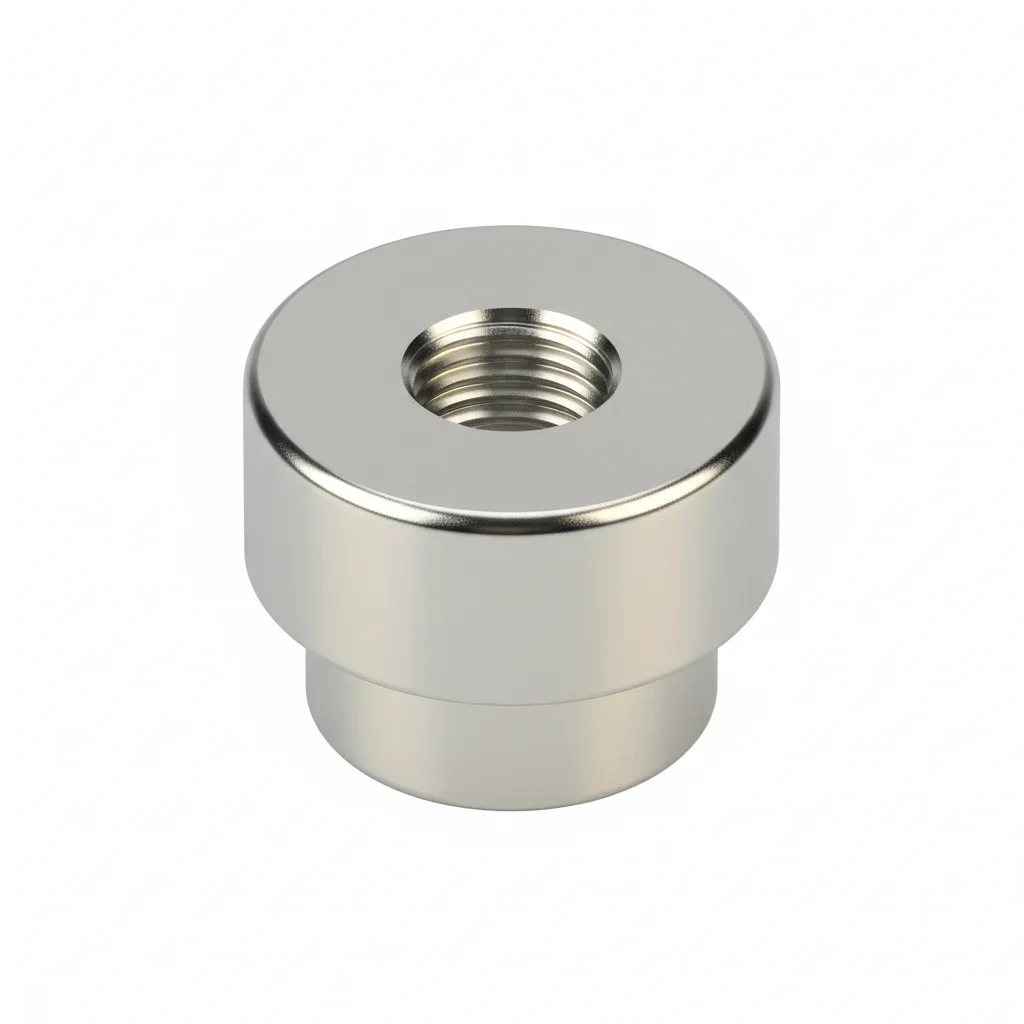
Select SMT nuts by thread and pitch, then check outside diameter, height, base geometry and PCB pads. Compare the drawings for SMT nuts, SMD nuts and surface mount threaded standoffs. Threaded insert is also used for other installation methods, so specify the intended PCB surface-mount assembly.
| Item | Information and conditions |
|---|---|
| Thread and outline | The selection table lists M2 × 0.4, M2.5 × 0.45, M3 × 0.5 and M4 × 0.7. Outside diameter, height and thread are separate parameters; confirm each against the model drawing. |
| Pads and fastening | Provide board thickness, hole and pad dimensions in mm, screw length, engagement depth and mechanical load. Validate tightening torque in N·m on the intended PCB and soldered assembly. |
| Packaging and placement | For SMD nuts in tape and reel, confirm tape width, feed orientation, pickup surface and reel quantity. Review the reflow profile, solder and plating against assembly requirements. |
A different height changes screw engagement and clearance. Even with the same thread, compare the base, pads, board hole and loads after reflow before confirming a replacement.
Provide a part number or thread, target height and base dimensions, PCB pad drawing and screw assembly requirements. Include sample and production quantities, material, finish and packaging; confirm the drawing revision and lead time.
Widely used in PCB mounting for various electronics
Phone, tablet, laptop internal mounting
Base station, router, switch PCB mounting
ECU, dashboard, ADAS modules
Portable medical instruments
PLC, HMI, sensor modules
BMS boards, inverter control units
Share a part number or thread, height, base dimensions and PCB pad drawing for SMT nut selection or customization. Confirm tape dimensions, pickup method, sample quantity and lead time for the model and assembly.