


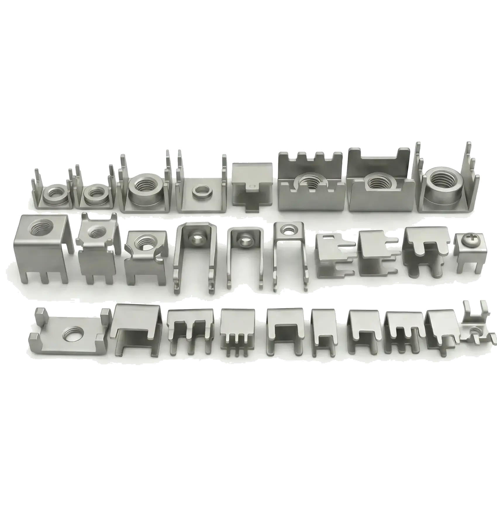
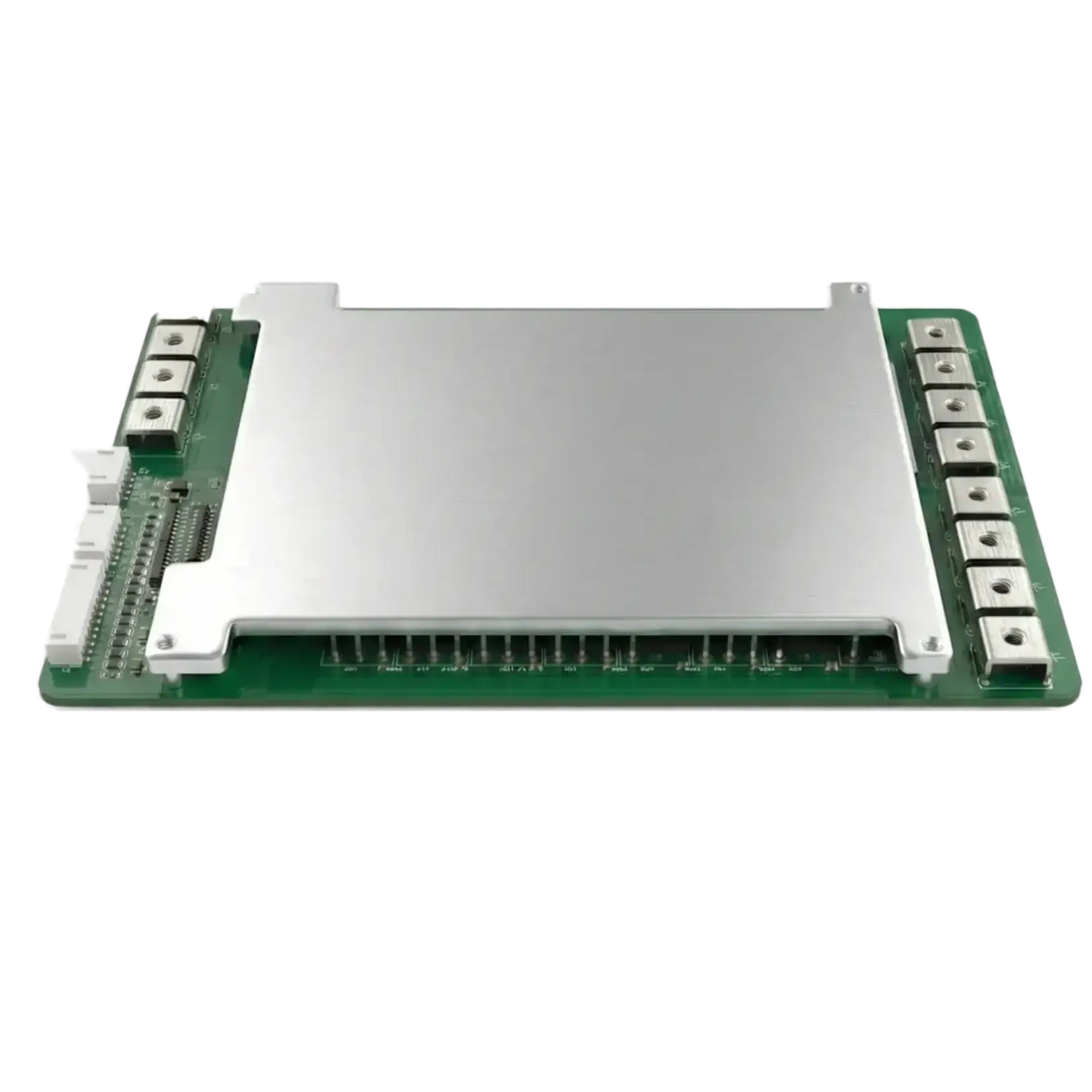
HCSP terminals connect PCBs to external conductors. Material, pin geometry and threads vary by model; select the soldering process against the drawing. Verify resistance, temperature rise and mechanical strength with the intended PCB pads, copper thickness, solder and fastening conditions.
Detailed product parameters
| Material | T2 Copper, H62 Brass, C1100, C2680 |
| Thickness | 0.5mm - 5.0mm |
| Thread Size | M3-M10 (Internal/External) |
| Plating | Matte Tin, Nickel, Silver |
| Mounting | THR, Wave Soldering, Press-fit |
| Torque Requirements | Verify by thread, material and mounting method |
| Packaging | Tray, Tape & Reel (SMT) |
| Compliance Documents | Confirm applicable documents by model and batch |
Select PCB solder terminals by thread, pin geometry, board thickness, material and soldering process. M3, M4 or M6 describes a threaded interface; confirm the available model against a drawing. For a custom PCB solder terminal, include the external conductor connection and mechanical loads to review board mounting.
| Item | Information and conditions |
|---|---|
| Connection and pins | Specify internal or external thread, pitch, pin count and spacing in mm, board thickness, hole diameter, pads and conductor contact dimensions. |
| Material and soldering | State material grade, plating and coating thickness requirements. Confirm through-hole reflow, wave soldering or another assembly method for the actual pin geometry and drawing. |
| Testing and purchasing | Include continuous current in A, peak duration in ms, permitted temperature rise in K and fastening loads. Submit sample and production quantities, document requirements and target delivery date. |
Identify the PCB input or output, working voltage and current, then check thread, pins and insulation boundaries. An application name helps describe the requirement; validate samples on the actual PCB and connection.
Send a dimensioned drawing, material and quantity for selection or custom review. Available models, sample arrangements, packaging and lead time are confirmed in the project response.
Widely used in New Energy & Power Electronics
Main board to busbar connection
High current I/O terminals
Internal connection of HV PDU
Server PSU, Telecom power modules
IGBT connection, 3-phase output
AC/DC power module connection
Share dimensions, thread, board thickness, mounting method and quantity to identify catalog or custom options. Samples, tooling, packaging and lead time are confirmed per project.