


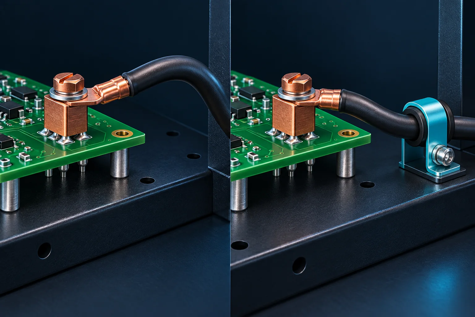
If a PCB solder terminal tilts after a heavy cable is fitted, examine the cable's free shape, restraints and loads relative to the soldered region. Force is measured in N; moment is measured in N·m. The same force produces a larger moment about a specified reference when its perpendicular lever arm increases. Passing a wire-crimp pull test does not establish solder-joint resistance to assembly side loads.
Draw the force line before using a lever arm
OpenStax's torque explanation gives M=rFsinθ, equivalently M=Fℓ⊥. The perpendicular distance is measured from the chosen reference to the force line. Define that reference, such as a specified point in the soldered region, rather than treating total cable length as the lever arm.
For a hypothetical 10 N force and 30 mm=0.030 m perpendicular arm, the moment is 0.30 N·m. With the same assumed force and a 10 mm arm, it is 0.10 N·m. These are static geometry examples. Cable reaction force changes with routing, clamping and temperature, so moving a clamp does not guarantee the actual moment becomes one-third.
Separate loads from strength reports
| Record | Unit or definition | Boundary |
|---|---|---|
| Applied force | N, direction and application point | Magnitude alone does not define moment |
| Moment about a reference | N·m with perpendicular arm | Different from screw-tightening torque |
| Crimp pull result | N for the specified wire and crimp | Does not validate solder-joint side loading |
| Assembly validation | Displacement, board bending, cracking and electrical changes | Needs real supports and an agreed load procedure |
Trace where a cable restraint sends the force
The Phoenix Contact strain-relief accessory example belongs to a defined connector system. It does not establish compatibility with Hongchuan metal terminals or demonstrate that every restraint transfers load to the enclosure.
Trace the cable, clamp, bracket, PCB supports and chassis. A clamp mounted on the same thin board may merely change where the force enters the PCB. Check insulation damage, forced tight bends and stored cable force released during maintenance. Use the cable manufacturer's bend requirements for the actual installation; do not assign one universal bend multiple to every wire size.
Make an assembly comparison reproducible
With equipment safely isolated, allow the cable to follow its actual route. Record terminal height, tilt and PCB support before and after connection. Compare approved restrained and unrestrained arrangements with the same cable specification, length, lug and fastening procedure. If loads are applied, document point, direction, rate, hold time and residual deformation after unloading.
Inspect more than complete detachment. Evaluate solder, pads and substrate according to risk, alongside baseline and post-test continuity or low-resistance measurements. Define mechanical and electrical limits for the actual assembly. Stop according to the approved procedure if cracks or abnormal displacement develop; a destructive maximum is not a daily assembly setting.
Include cable data in the inquiry
For PCB solder terminals, provide board thickness, pad geometry, cable conductor area and outside diameter, exit direction, restraints, space drawings and load requirements. M3, M4 or M6 in a request is a connection parameter awaiting confirmation, not proof of an available model or current rating.
Prepare wire information using AWG, conductor area and outside-diameter definitions. A cable construction or material change can require routing and load review even when conductor area stays the same.
Questions
Will more tightening torque straighten the terminal? Investigate external force, supports and interference first. Additional torque can introduce another assembly load.
Is a shorter cable always safer? A short cable may be harder to bend. Check actual reaction force, restraints and supports rather than length alone.
The AI-generated cover compares structural restraint concepts, not Hongchuan product photographs or measured tests. Examples do not specify allowable moment, pull force or tightening torque.