


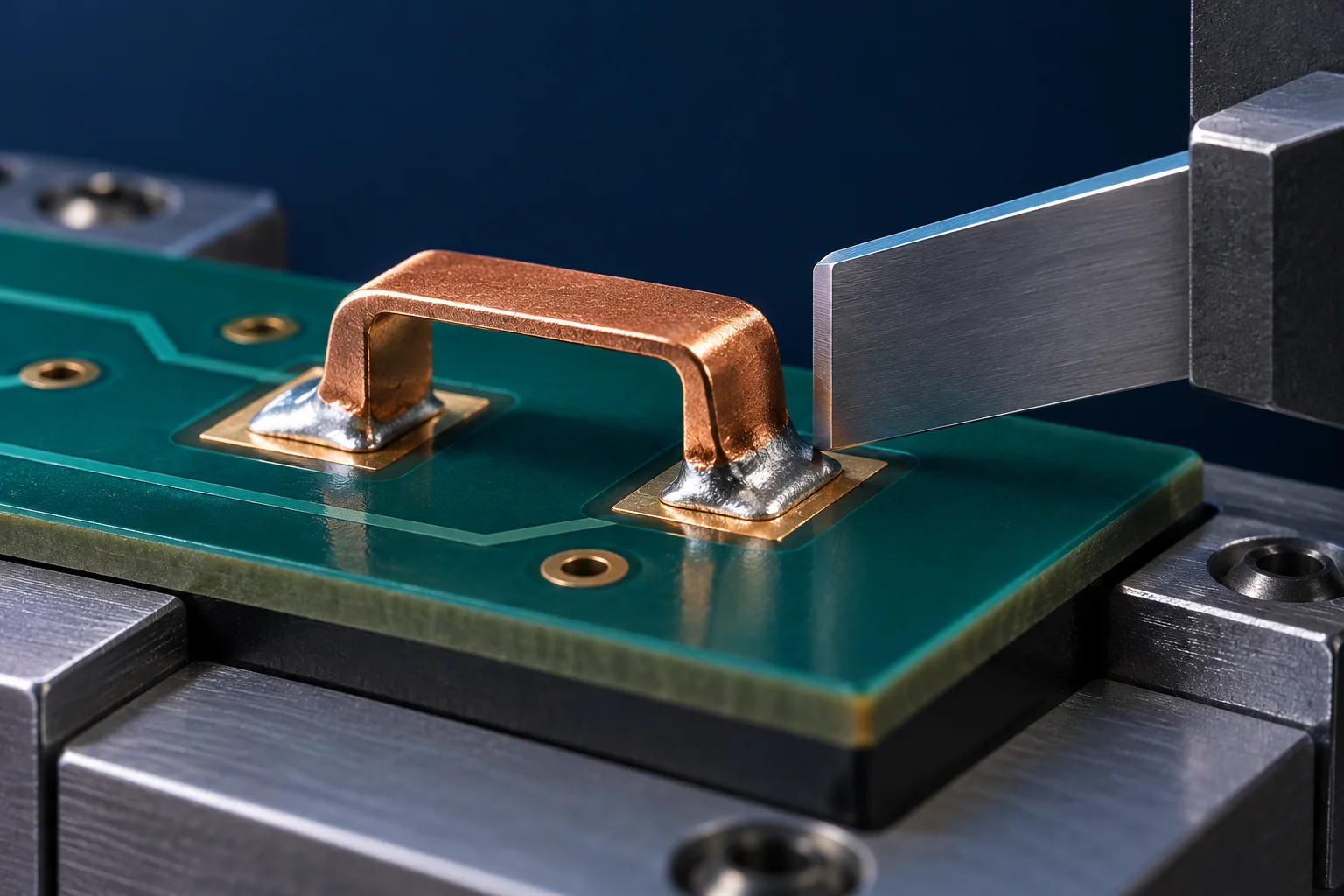
A surface mount PCB jumper's peak shear force is comparable only when tool height, speed, direction, board support and specimen condition are defined. Pushing the top of a bridge differs from loading near a soldered foot. A report stating only “100 N shear force” does not establish solder-joint strength or a production acceptance limit.
Define what the tool contacts
Xyztec's SMD shear introduction describes configuration options including tool orientation, deep access and heated sample holders. A raised copper jumper needs a drawing showing the tool relative to the metal foot, solder and PCB surface. “Side push” is not a complete method.
Define height h from an agreed board-surface reference in mm or μm. Record edge shape, contact width, direction and clearance. Contact with solder, bridge metal or substrate creates different loading conditions. A high contact point may add bending and peeling; do not automatically label the result pure shear.
Minimum information for a reproducible comparison
| Item | Record | Comparison risk |
|---|---|---|
| Loading geometry | Tool, height, direction and photograph | Comparing different contact locations |
| Motion | Approach process, test speed and units | Assuming set speed describes actual contact |
| Board support | Fixture, span, thickness and clamping positions | Board bending changes the load path |
| Specimen state | Jumper, solder, pads, reflow and conditioning | Comparing different assemblies as one component |
| Results | Force-displacement trace, peak, fracture images and sample count | Means conceal different failure modes |
Force and nominal stress are different quantities
100 N is a force. Dividing it by an assumed 4 mm² gives 25 N/mm², or 25 MPa. This is only a unit example. Without a defined area, load distribution and fracture plane, that quotient must not be reported as solder material shear strength. The two feet of a jumper may not carry equal loads at the same instant.
Retain raw force-displacement data and the method first. If nominal stress is required, agree how area is determined, how both feet are counted and where the metric applies. These hypothetical values are not Hongchuan results or universal acceptance criteria.
Use failure location to guide interpretation
Xyztec's solder-ball shear explanation separates material, pad and interface failures. It supports recording fracture morphology, but its ball geometry and referenced method must not be transferred directly to a raised copper jumper.
Classify metal deformation, solder fracture, interface separation, copper-pad peel and substrate damage. If the PCB fails first, the test identifies that failure path in that assembly; it does not reveal the intrinsic solder-strength limit. Explain different failure groups before comparing peaks.
Plan an initial controlled comparison
A competent laboratory and the responsible designer should define a guarded destructive-test fixture. Keep jumper, PCB and soldering lots constant, fix direction, support and speed, then vary tool height or one other factor at a time. Agree sample counts and prevent the tool scraping the board. Never perform destructive side-loading on energized boards.
For a surface mount PCB jumper inquiry, include pad geometry, solder information and loading photographs. See depaneling strain validation for a different assembly-process concern. A single shear test does not replace vibration or thermal-cycling evaluation.
Questions
Does a higher peak always mean better reliability? Check method consistency and fracture location first. A destructive peak alone does not predict service life.
Can a ceramic component's force threshold be reused? The responsible design and validation team must establish applicable methods and criteria for the actual jumper structure.
The AI-generated cover is a side-loading concept, not Hongchuan laboratory equipment or a test result. The unit example is not a shear-strength claim.