


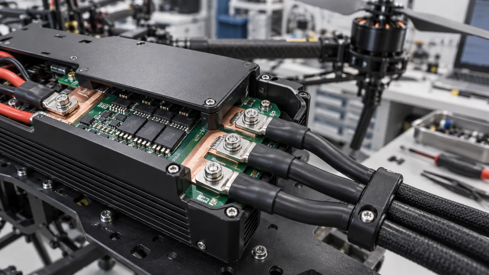
Quick answer: A drone ESC high-current PCB terminal must handle battery peak current, three-phase motor current, low mass, cable support and flight vibration. The terminal can be compact, but pad exit, copper path and strain relief cannot be reduced below a reliable margin. Validate peak temperature, segmented drop, joint strength, cable bending and post-vibration resistance.
Questions answered on this page
- Why does a drone ESC need a dedicated high-current PCB terminal?
- How should battery input and three-phase output differ?
- Which dimensions should not be reduced for weight?
- How can cable bending stay away from solder joints?
- How should a compact ESC be tested?
Application context
A drone ESC has battery positive and negative input plus U/V/W motor output. Battery input sees capacitor ripple and acceleration peaks; phase output sees PWM commutation and dynamic motor-cable load. Hongchuan supplies PCB welding terminals and SMD busbars. Provide peak and continuous current, PWM, cable, board, copper, spacing, enclosure and support.
Input and phase output differences
| Position | Condition | Focus |
|---|---|---|
| Battery input | DC, ripple and peak | Drop, cooling and capacitor loop |
| Phase output | PWM and cable motion | Phase match, support and vibration |
| Solder joint | Thermal and board cycling | Fill, pad and load path |
| Housing interface | Service and impact | Tool access, clamp and insulation |
Weight reduction and measurement
The PCB interface is often the hidden limit. A narrow pad exit raises current density; too few vias heat during layer change; small spacing hurts insulation and assembly. Match path length, layers, copper width and contact area across U/V/W. Use the housing or clip to carry cable load. See pad-exit and via-array troubleshooting.
Peak and PWM temperature testing
A DC bench test does not cover PWM commutation, ripple or dynamic load. Test battery input at rated and peak current and the real motor phase waveform under hover and acceleration. Measure terminal body, solder, copper exit, lug and nearby MOSFET temperature. Use segmented four-wire drop to separate terminal, solder, copper and cable. Compare phase current when temperatures differ.
Vibration and strain relief
Motor vibration, frame resonance and cable motion repeatedly load the terminal. Use flexible retention and strain relief near the terminal rather than a hard cable bend at the solder joint. Before and after vibration inspect cracks, board delamination, terminal looseness, clamp wear and contact resistance. See PCB terminal solder-process window.
FAQ
Is a lighter terminal always better?
No. Balance mass against section, solder area, spacing, support and temperature.
Can one temperature result cover all phases?
Only after paths, pads, solder, cooling and phase current are shown to match.
How should samples be specified?
Provide battery and phase peak current, cable, board, copper, PWM and mounting orientation. Use the high-current PCB hardware selection guide.