


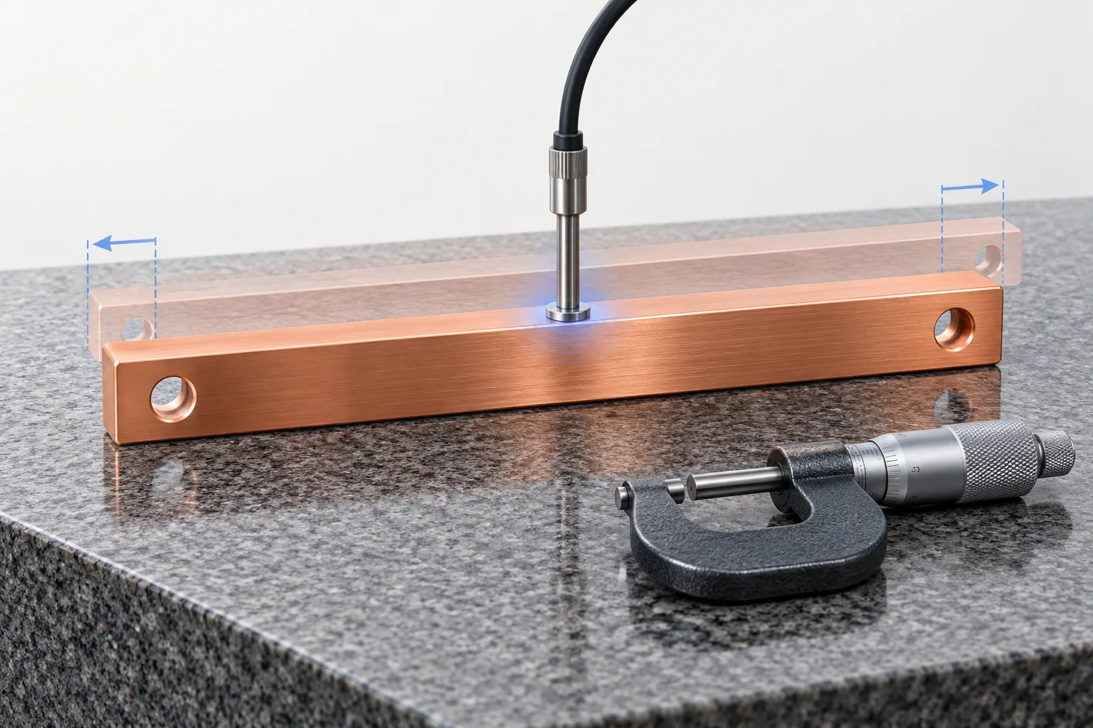
Confirm the drawing's reference temperature before accepting PCB copper busbar dimensions. If a dimension refers to 20°C but the part is measured elsewhere, assess whether thermal expansion is negligible or apply an approved correction. Retain the part temperature, original measurement and corrected result; an air-conditioning setting is not a measurement of the part.
Define the dimension before correcting it
NIST's engineering metrology guidance identifies 20°C as the reference temperature for industrial dimensional measurements and discusses expansion corrections away from it. Follow any explicit alternative on the drawing. This is a length correction, not electrical-resistance normalization: the quantities and coefficients differ.
Identify whether the requirement concerns overall length, hole-centre distance or a formed functional span. A temperature calculation cannot reconcile different dimension definitions or convert a projected length into a developed length. Match the measurement points to the controlled drawing revision first.
A hypothetical expansion calculation
Assume a uniform, freely expanding part has a length of 50.000 mm at 20°C. For this example only, assume a constant linear expansion coefficient α=17×10−6/K between 20°C and 35°C. The 15 K rise gives ΔL=αL20ΔT=0.01275 mm, or 12.75 μm. Its ideal length becomes 50.01275 mm. The coefficient is an illustrative input, not a guaranteed Hongchuan material property.
The reverse calculation is L20=LT/[1+α(T−20°C)]. It applies only within the stated linear model and measurement conditions. Extra decimal places in a calculation do not establish instrument accuracy or eliminate uncertainty in temperature and coefficient.
| Record | Units or identification | Purpose |
|---|---|---|
| Original dimension | mm, drawing revision and feature ID | Preserve the uncorrected observation |
| Part temperature | °C, location and time | Establish departure from reference |
| Expansion coefficient | 1/K, source and temperature range | Document the correction input |
| Corrected result | mm, method and uncertainty | Support the agreed acceptance decision |
Check the measurement system as well
The example assumes the measurement system has already dealt correctly with its own temperature effects. Instruments and reference artifacts also respond to temperature. Follow their measurement procedure and avoid correcting an output twice if software has already compensated it.
NIST's research discusses uncertainty in part temperature and thermal expansion coefficients. For inspection planning, confirm the temperature state of a part transferred from machining or handling. A room thermometer alone does not demonstrate uniform part temperature. There is no universal stabilization time in this article.
Connect the result to the purchase specification
For SMD and SMT PCB busbars, agree reference temperature, free or constrained state, support, measuring force and coefficient evidence. If thermal effects matter relative to tolerance, review conditions and uncertainty rather than silently changing the drawing limits.
The related dimensional uncertainty and guard-band guide addresses borderline acceptance. Temperature correction establishes the reference of the result; it does not replace the approved decision rule.
Questions
Must every workshop be exactly 20°C? Assess the tolerance, temperature difference, material and method together.
Can an uncorrected reading simply be labelled “at 20°C”? No. The report needs evidence of measurement at reference temperature or a valid correction.
Sources
NIST engineering metrology temperature guidance; NIST research on dimensional uncertainty at nonstandard temperatures.
The AI cover exaggerates expansion for illustration; it is not a Hongchuan product photograph or inspection record. Example values are not material, tolerance or measurement-capability commitments.