


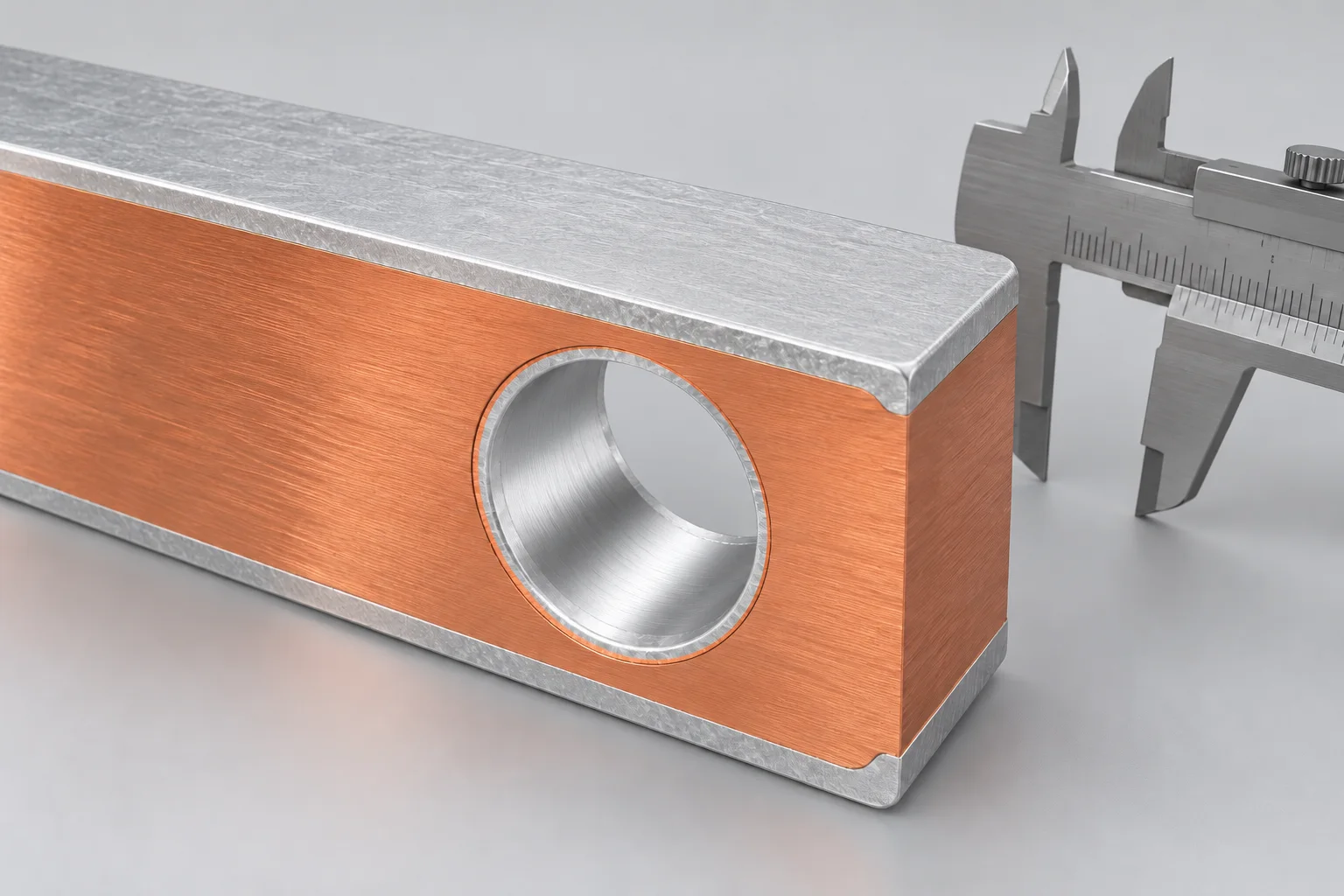
A PCB busbar drawing should state whether dimensions apply before plating or to the finished part. A single-face coating thickness is not automatically the increase in total part thickness. Coating inside a round hole can reduce its diameter. Specify finished fit dimensions separately from layer requirements rather than relying on “plate to drawing.”
Attach each dimension to a manufacturing state
SPIROL's public slotted spring pin guide explicitly states that dimensions apply before plating. It is an example of clear documentation for a different component type, not a dimensional rule for Hongchuan busbars or all metal hardware.
If a copper busbar drawing specifies 2.000 mm, clarify whether it means base-metal thickness, finished overall thickness or a local feature. An RFQ should separate base material and temper, underlayers, top finish, layer requirements and finished dimensions. Tin plating and nickel plating are different finishes, not interchangeable labels.
Two coated faces add two thicknesses
Consider an ideal geometric example. A base is 2.000 mm thick and receives 5 μm on each of its two opposing flat faces. Ignoring pretreatment removal, deformation and other layers, the final thickness is 2.000+0.005+0.005=2.010 mm.
For an initially 4.000 mm straight circular bore, assume a uniform 5 μm radial build-up on the inside wall. With no other changes, its final diameter is 4.000−2×0.005=3.990 mm. This model concerns a smooth, unthreaded bore. Do not apply it directly to thread pitch diameter, chamfers or an uneven hole entrance.
| Ideal feature | Meaning of 5 μm | Dimensional effect |
|---|---|---|
| Opposing flat faces | One layer on each face | Total thickness grows by 10 μm |
| Circular bore wall | Radial growth into the opening | Diameter decreases by 10 μm |
| Multiple layers | Each layer separately defined | Establish the complete stack first |
| Selective plating | Only specified areas are coated | Analyse the actual controlled surfaces |
Coating data do not replace finished inspection
The calculation does not establish that real coatings are uniform. Hitachi's guidance for irregular-part XRF measurements highlights positioning, surface geometry and measurement distance. A thickness result on one flat face is not automatically a result for the bore, edge or opposite face.
Keep finished dimensional inspection and coating inspection as separate records. For dimensions, identify the instrument, feature locations, temperature and constraint state. For coatings, identify the layer stack, location, method and result. Do not casually strip a part to infer its original dimensions: preparation may change the surface. Approve sampling and methods before destructive analysis.
Resolve the fit in the purchase documents
For custom SMD PCB busbars, provide the mating-part requirements and identify fit-critical holes, thicknesses and contact regions. Agree which dimensions are accepted after final plating and which base-metal data come from in-process records. Keep limits, methods and disposition rules in the same controlled revision.
The related XRF coating thickness report guide addresses layers and measurement locations. This page addresses their dimensional consequences. Passing one requirement does not prove that the other has passed.
Questions
Is “5 μm plating” a complete specification? Identify material, individual versus total layer thickness, thickness definition, locations and acceptance criteria.
Does a correct pre-plate hole guarantee assembly fit? Check the specified final state, mating tolerances and subsequent operations.
Sources
SPIROL guide: explicit pre-plating dimension notes; Hitachi guidance on positioning irregular parts for coating measurement.
The AI cover exaggerates coating thickness to explain geometry; it is not an actual construction or inspection image. Dimensions and 5 μm inputs are illustrative, not Hongchuan product or acceptance specifications.