


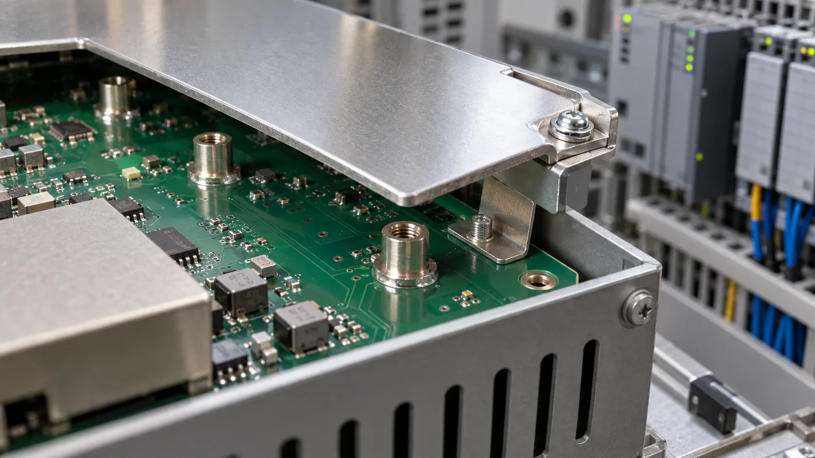
Quick answer: An SMT nut for a PLC EMI shield must satisfy fastening strength and grounding as separate functions. The nut pad spreads screw load into the PCB; the shield edge, spring or defined ground point establishes continuity. Review board thickness, pad, nut height, thread protection, shield tolerance, torque and post-cycle ground resistance together.
Questions answered on this page
- Why use SMT nuts for a PLC shield?
- How should fastening and grounding be separated?
- How can thread contamination and pad lift be prevented?
- How should torque be set for repeated service?
- How should the shield ground path be verified?
Application context
PLC, remote-I/O and industrial-communication boards use metal shields around clocks, transceivers, isolated power and relay drivers. An SMT nut can be placed through SMT and reflow, then a screw attaches the shield or bracket. Hongchuan supplies SMT nuts and PCB hardware. Provide board, screw, shield, pad, ground method, torque and reflow profile.
Separate fastening and grounding
| Function | Parts | Metric |
|---|---|---|
| Fastening | Nut, pad, screw and shield | Torque, pull, shear and bend |
| Grounding | Shield edge, spring, ground copper | DC resistance and continuity |
| Manufacturing | Stencil, paste, placement and reflow | Offset, coverage and gauge |
| Service | Tool access and repeated fastening | Cycle count and drift |
A pull test alone does not prove shield grounding, and an initial ground reading does not prove that the pad can survive service torque.
Board, height and pad matching
Board thickness determines bottom support, pad area and bend under screw load. Match nut height to shield flange, screw length, devices and thermal clearance. A small pad concentrates edge stress; an oversized pad can consume routing or HV spacing. Control paste around the thread with the stencil. See SMT nut pad and torque validation.
Ground continuity testing
After assembly, measure low resistance between each nut, the far shield edge, springs, PCB ground and chassis point. Record before fastening, after fastening, after thermal cycling and after repeated service. Include the far edge because contact pressure and oxidation can differ from the nut area. If immunity remains unstable, inspect shield gaps, cable entry, spring pressure and high-frequency return path rather than simply adding nuts.
Reflow and production
Large metal nuts can change local heating and wetting. After reflow inspect offset, base coverage, thread cleanliness and pad edge. For critical lots, sample thread gauge, pull, torque and ground continuity. Define stencil opening, paste volume and profile limits.
FAQ
Does a strong solder joint prove shield grounding?
No. Joint strength and shield grounding are separate measurements.
Is higher PLC shield torque better?
No. Excess torque can lift pads, crack rings, bend the board or deform the shield. Set a window for the board and structure.
How should samples be specified?
Provide board, screw, shield, pad, ground spring, target torque and reflow process. Start with the SMT nut product page.