


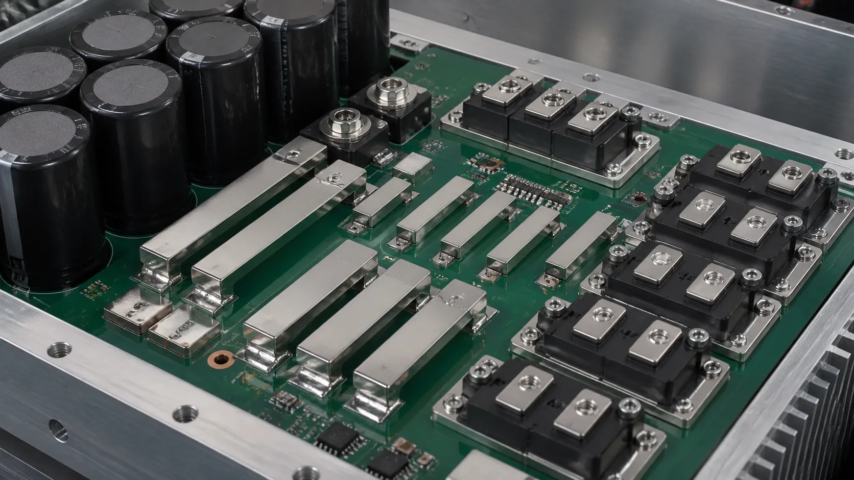
Quick answer: Select a wind-converter SMD busbar by reviewing DC-link current, ripple, IGBT or SiC layout, PCB exits, vias, reflow heat, insulation spacing, cooling and vibration. Validate with segmented drop, stable temperature, X-ray, thermal cycling and post-vibration resistance, not thickness alone.
Questions answered on this page
- Why use SMD busbars on a wind converter power board?
- How should the DC-link to module path be planned?
- How should body, pad exit and vias be checked together?
- How should reflow heat and joint reliability be controlled?
- What should be rechecked after ripple, vibration and thermal cycling?
Application context
Wind converters may use power boards on both machine and grid sides. SMD busbars connect DC-link capacitors, IGBT or SiC modules, rectifiers and high-voltage terminals over short paths. Hongchuan supplies SMD busbars matched to current, board, pads and reflow requirements.
Electrical, insulation, thermal and mechanical boundaries
| Boundary | Confirm | Validation |
|---|---|---|
| Electrical | Continuous, peak, ripple and overload | Drop, rise and loss |
| Insulation | Voltage, creepage and clearance | Layout tolerance |
| Thermal | Modules, heat sink, airflow and neighbors | Stable thermal map |
| Mechanical | Cabinet and nacelle vibration | Post-vibration joints |
Pad exits are a common bottleneck
A stable bar section does not mean the PCB can receive the same width. Review the copper transition, inner copper, layer-change vias, slot edges and nearby HV metal. A wide bar into narrow copper creates a pad-exit hot spot and can unbalance parallel branches. Measure body, joints, pad exit, vias, inner copper and module terminals separately. See pad-exit and via-array troubleshooting.
Reflow and long-term validation
Thick copper changes heating at the pads. Validate stencil, paste, flatness, support and profile with thermocouples at the bar, pads and nearby devices. Use X-ray for coverage and voids and cross-section when needed. Under real DC-link ripple, run stable current, thermal cycling, vibration and shock, then repeat drop, temperature and joint inspection. See SMD busbar reflow inspection.
FAQ
Is continuous current enough for selection?
No. Ripple, overload, cooling, insulation and vibration also affect the design.
Is a cool busbar body sufficient?
No. Joints, pad exits, vias or inner copper may be the bottleneck. Measure segmented drop.
How should the specification be confirmed?
Provide current, ripple, board, copper, module layout and reflow conditions. See the high-current PCB hardware selection guide.