


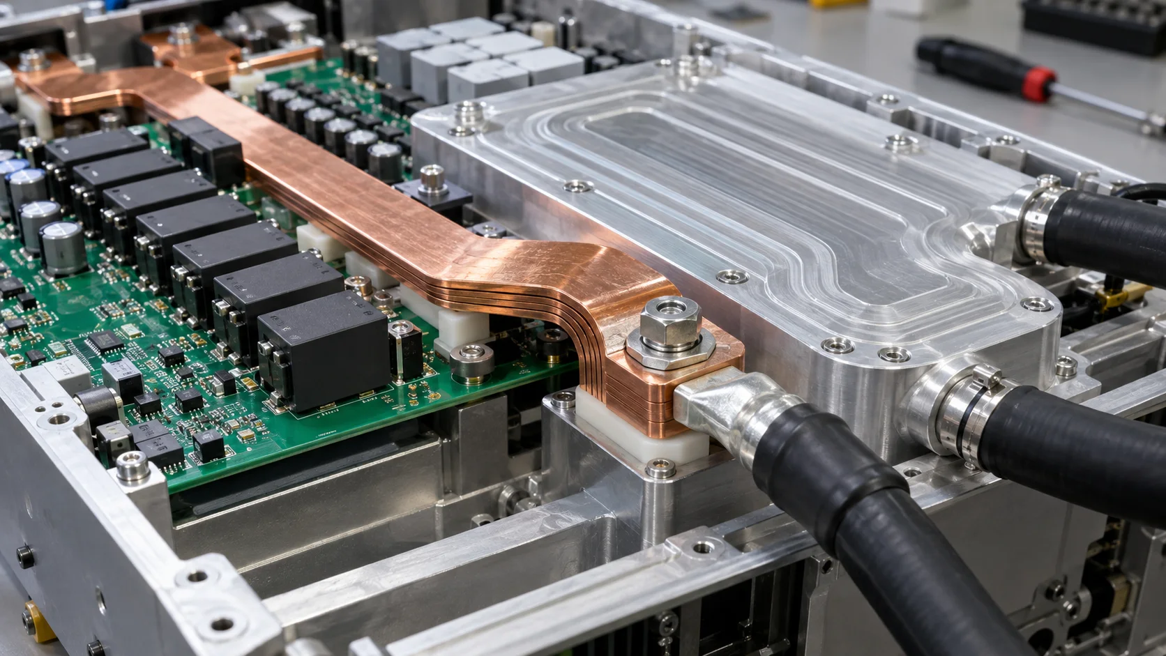
Quick answer: Select a high-current PCB welding terminal for a liquid-cooled EV charging module by checking terminal drop, pad-exit heating, temperature gradients near the cold plate, cable force and condensation spacing. Cooling removes heat but can also bring cold surfaces near joints and insulation.
Questions answered on this page
- Why do liquid-cooled charger modules still need PCB welding terminals?
- How should terminal, busbar and cold plate reduce drop and heat?
- How should temperature difference, condensation and clearance be controlled?
- What should be checked after soldering a high-mass terminal?
- How should powered and sealing checks be combined?
Application context
DC fast-charging power modules place power devices, copper bars, cold plates, capacitors and external cables in a compact enclosure. A PCB welding terminal connects the power board to a bar or cable, but its position must be coordinated with the cold plate, insulation, hoses, fittings and service space. Hongchuan supplies high-current PCB welding terminals matched to current, ripple, cable direction, copper, cooling, temperature and sealing.
Five selection parameters
| Parameter | Confirm | Failure sign |
|---|---|---|
| Electrical | Continuous, peak, ripple and allowed drop | Loss or terminal hot spot |
| Thermal | Cold-plate location, interface resistance and airflow | Pad-exit gradient |
| Mechanical | Cable bend, fitting support and board support | Joint pull or board bend |
| Insulation | Condensation path, height and housing clearance | Leakage or creepage risk |
| Manufacturing | Stencil, solder profile, cleaning and inspection | Uneven wetting or residue |
Measure drop and temperature in sections
Do not measure only at the board ends. Record terminal ends, solder legs, pad exits, busbar joint, cable crimp and cold-plate area, using four-wire drop measurements. Cover rated and peak current at maximum coolant temperature and minimum flow. If the pad exit is hotter than the terminal, inspect copper transition, inner receiving layers, vias and solder coverage. See pad-exit and via-array troubleshooting.
Condensation near the cold plate
Coolant inlet temperature, humidity and shutdown state can place metal below dew point. Check insulation, drainage, sealing and creepage around terminals, joints, bars and exposed ground copper. Evaluate coolant leakage, service residue and long-term contamination on supports. The absence of visible droplets is not the only acceptance criterion.
Soldering, sealing and service validation
Large terminals absorb heat and change wetting. After reflow or wave soldering inspect coverage, voids, offset, verticality and board support. Under coolant pressure, temperature cycling and powered load, repeat drop, temperature, insulation and appearance checks. Use X-ray and cross-section inspection when internal solder quality matters.
FAQ
Does a cold plate allow a smaller terminal?
No. Terminal capability must still cover current, drop, pad, environment and worst cooling conditions.
Is leak testing the only critical liquid-cooling test?
No. Check condensation, insulation, contact resistance and powered temperature as well.
How should samples be specified?
Provide current, ripple, board and copper, cable, cold plate, temperature, flow and sealing details. Start with the welding terminal product page.