


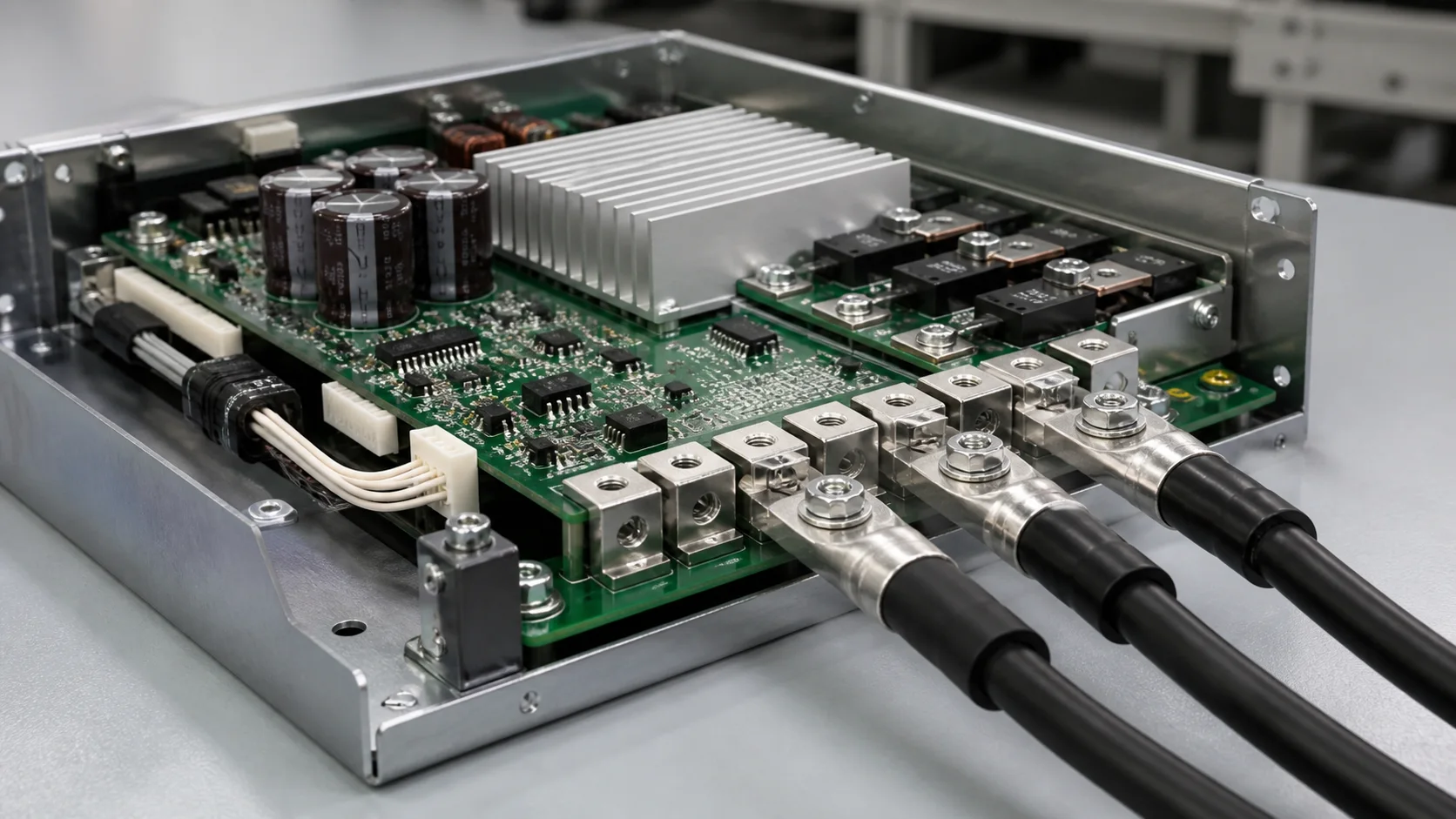
Quick answer: Select a PCB welding terminal for an industrial-robot servo drive by checking continuous and pulsed brake current, pad capacity, copper exits, terminal support, cable bend, cabinet airflow and the motion cycle. A cool terminal body does not prove that the pad exit or cable root is cool.
Questions answered on this page
- Why use PCB welding terminals in servo brake circuits?
- How do continuous and pulsed current affect selection?
- How do vibration and cable force reach the solder joint?
- How should the pad exit and terminal root be tested?
- What should production inspection record?
Application context
Robot joints and external axes are powered by servo drives. PCB welding terminals may carry motor phases, DC bus, brake resistors or brake units in a compact cabinet. Brake-resistor loads are often pulsed, so the terminal should be evaluated over the real duty cycle rather than one steady-current value. Hongchuan supplies PCB welding terminals matched to waveform, cable, board, copper, pad, height and mounting direction.
Trace the complete current path
| Area | Review | Risk |
|---|---|---|
| Terminal | Section, material, finish and contact length | Resistance hot spot |
| Pad exit | Copper transition, inner layers and vias | Pad-edge heating or lift |
| Cable side | Gauge, bend, clamp and pull | Side load on joint |
| Cabinet | Airflow, heat sources and clearance | Heat accumulation |
Measure any neck-down between the terminal leg and the main PCB copper together with vias and inner copper. See high-current pad-exit troubleshooting.
Temperature under brake pulses
Brake circuits may conduct during deceleration, emergency stops and load changes. Use a full robot cycle with acceleration, motion, deceleration, stop and repeated starts. Measure the terminal, solder leg, pad exit, adjacent copper, cable lug and insulation while recording drive temperature and airflow.
- Use the real current waveform for continuous, peak and repeated pulse states.
- Fix the cable in its final position so the sample has the correct mechanical load.
- Compare terminal direction and airflow position to separate resistance from cooling effects.
- Measure voltage drop with a four-wire method and correlate it with temperature rise.
Vibration, cable support and soldering
Robot motion repeatedly bends cables. Cable-chain movement, clamps and assembly tolerance can transfer force into the PCB terminal. Add independent cable support or strain relief so the solder joint does not carry cable weight and bending force. Inspect solder coverage, leg fill, terminal verticality and board-side protrusion. Validate the actual board and thermal process; use visual, cross-section, pull and continuity checks, with X-ray inspection guidance when internal coverage matters.
Production acceptance
| Item | Record |
|---|---|
| Dimensions | Position, height, hole and coplanarity |
| Soldering | Coverage, wetting, voids and verticality |
| Electrical | Low resistance, withstand requirement and powered drop |
| Mechanical | Cable support, pull, post-vibration appearance and resistance drift |
FAQ
Is a terminal rating above motor current sufficient?
No. Include brake pulses, pad exit, cabinet temperature, cable force and duty cycle.
Why can the terminal be cool while the pad is hot?
A reduced solder-leg or copper transition, insufficient vias or poor heat spreading can create the hot spot.
How should samples be specified?
Provide waveform, cable, board, copper, pad, direction and support details. Start with the welding terminal product page.