


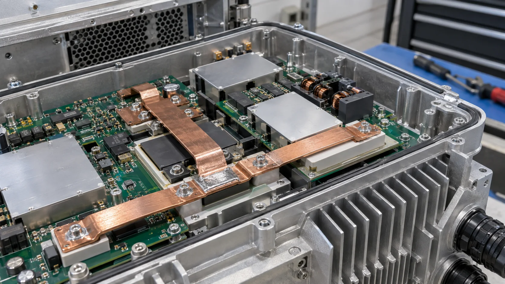
Quick answer: Select an SMD busbar for a 5G outdoor base-station power board by tracing the module output, surge protector, filter capacitors, PCB copper and chassis ground as one path. Validate steady heating, transient drop, spacing, reflow, condensation and salt exposure.
Questions answered on this page
- Why use an SMD busbar instead of a long PCB copper run?
- How do surge and high-frequency pulses affect the bar and pad?
- How should airflow, spacing and condensation be reviewed?
- How do salt and finish affect contact resistance?
- What belongs in prototype and production inspection?
Application context
Outdoor 5G radio units place AC/DC, DC/DC, surge protection, filters and RF power in a compact metal enclosure. An SMD busbar connects power modules with capacitors or protection devices, reducing long copper drops and loop parasitics while preserving boundaries for cooling, shielding and assembly. Hongchuan supplies SMD busbars matched to voltage, current waveform, copper, orientation, housing, environment and finish.
Four design boundaries
| Boundary | Confirm | Failure sign |
|---|---|---|
| Current | Continuous, peak, ripple and allowed drop | Module drop or hot spot |
| Transient | Surge path, protection and return area | Pad stress or ringing |
| Environment | Temperature, condensation, salt and contamination | Corrosion or rising resistance |
| Manufacturing | Stencil, placement, reflow and inspection access | Void, offset or poor wetting |
Trace the surge path
The surge path includes protector pins, busbar, pads, vias, chassis ground and connectors. Check for a short continuous path without narrow copper sections or undersized pads. For fast transients, review loop area, layer return and spacing in addition to DC drop. A necked pad exit may look acceptable in steady state but heat under repeated pulses and high ambient temperature. See pad-exit and via validation.
Heating, condensation and insulation
Outdoor airflow changes with seals, fans, heat sinks and cable blockage. Measure the bar, pad, protector, connector and nearby insulation at high ambient temperature and minimum airflow. For high-voltage or floating circuits, review bar thickness, burrs, solder protrusion, housing tolerance and condensation paths together. Finish should match the environment and mating materials; after salt, humidity and thermal cycling compare resistance, appearance, solder and plating rather than continuity alone.
Prototype to production
- Run actual current and surge waveforms at maximum ambient and minimum airflow.
- Inspect wetting, voids, end offset and copper transitions after reflow.
- After environmental exposure, repeat four-wire resistance, insulation and appearance checks.
- For production, record dimensions, pad coverage, key-point drop and temperature.
Use the high-current PCB hardware selection guide to organize the parameters.
FAQ
Does a wider bar always improve surge performance?
No. Path length, return, protector location, pads and vias matter as well.
Is continuity after salt exposure enough?
No. Check resistance drift, plating corrosion, solder joints and insulation surfaces.
What should be provided for samples?
Provide current and surge waveforms, stack-up, copper, housing, airflow, environment and finish. Start with the SMD busbar product page.