


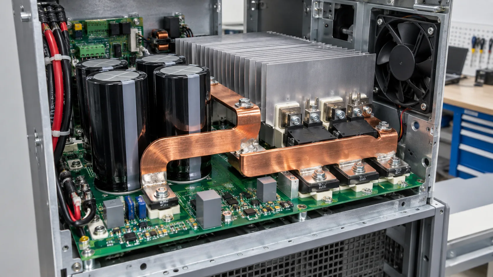
Quick answer: Select an SMD busbar for an industrial pump inverter by tracing the DC link, capacitors, power modules, airflow and motor cable. Start, reverse and stall protection create transient loads, so section alone cannot validate pad exit, drop, temperature or reflow.
Questions answered on this page
- Why use SMD busbars in pump inverters?
- How do start and stall currents affect the bar?
- How should the DC-link to module path reduce drop?
- How can pad exits and airflow avoid hot spots?
- How can reflow become a production window?
Application context
Industrial water, oil and cooling-pump drives connect rectifiers, DC-link capacitors, inverter modules and motor cables. An SMD busbar shortens board-level high-current paths and leaves defined space for heat sinks and insulation. Hongchuan supplies SMD busbars matched to motor power, waveform, DC voltage, ripple, stack-up, copper, pads, cooling and airflow.
Four control points
| Area | Review | Risk |
|---|---|---|
| DC link | Capacitor exit, positive/negative loop and bar entry | Drop and parasitics |
| Switch end | Pad, vias, module and heat sink | Exit hot spot |
| Busbar | Section, length, bend and spacing | Rise or insulation loss |
| Manufacturing | Stencil, placement, reflow and inspection | Void, offset or poor wetting |
Temperature under starts and stall protection
Cover cold start, rated speed, acceleration, reversal and stall protection. Measure bar, pad exit, vias, module end, capacitor end and nearby devices while recording DC-link ripple and segmented drop. If the exit is hotter than the bar, inspect copper neck-down, inner layers and via arrays. See pad-exit troubleshooting.
Reflow, cooling and production
Thick copper absorbs reflow heat and can create uneven wetting, coverage or end lift. Validate stencil, paste, flatness, board support and profile with the real board. Inspect coverage, voids, offset and support after reflow, using X-ray inspection as needed. Establish drop, temperature, ripple and insulation baselines, run the start, rated, reverse and stall cases at worst ambient and airflow, then sample dimensions, solder coverage, drop and temperature.
FAQ
Is motor rated power enough for sizing?
No. Start, stall, ripple, airflow and pad exit change the load.
Is thicker always better?
No. Balance reflow heat, spacing, flatness and assembly space.
How should samples be specified?
Provide power, waveform, DC voltage, ripple, stack-up, copper, pads and airflow. Start with the SMD busbar product page.