


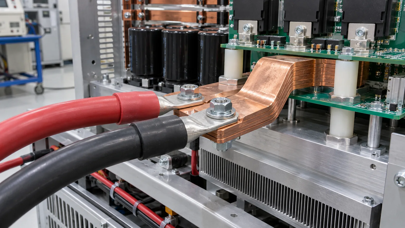
Quick answer: Select PCB terminals for an electrolyzer rectifier supply from long-duration current, ripple, load steps, bar path, pad exit, cabinet cooling, moisture contamination and insulation boundaries. Current rating alone does not prove stable resistance and temperature after long operation.
Questions answered on this page
- Why use PCB welding terminals in electrolyzer rectifier supplies?
- How do long current and ripple affect terminals and pads?
- How should bars, vias and cables form a low-resistance path?
- How do moisture and residue affect insulation?
- How should long-run service checks be built?
Application context
Electrolyzer systems connect rectifiers, filter capacitors, DC buses and the stack, with cooling, protection and measurement in the power cabinet. A PCB terminal connects the power board to a bar or heavy cable and must remain low resistance under long constant current and load changes. Hongchuan supplies high-current PCB welding terminals matched to current, ripple, duration, cable, board, copper, cooling, humidity and insulation.
Four boundaries
| Boundary | Review | Risk |
|---|---|---|
| Current | Continuous, ripple, load step and allowed drop | Terminal or pad hot spot |
| Thermal | Run time, airflow, cooling and nearby heat | Heat accumulation |
| Mechanical | Bar, cable, support and service pull | Joint fatigue |
| Environment | Moisture, condensation, residue and spacing | Leakage or corrosion |
Long-run drop and temperature
Cover cold start, rated constant current, ripple, load step, maximum cabinet temperature and worst cooling. Measure terminal, solder leg, pad exit, vias, bar joint, cable crimp and nearby insulation, and use four-wire segmented drop. After reaching thermal stability, compare drop and temperature drift over time. See pad-exit and via-array troubleshooting.
Soldering, moisture and service
Large terminals add solder heat mass. After reflow or wave soldering inspect wetting, coverage, voids, offset, verticality and board support; use X-ray inspection when needed. Check condensation, sealing, drainage and contamination around terminals, joints, bars and exposed ground copper. Keep cable and bar support independent of the PCB. Establish resistance, drop, insulation and temperature baselines, run long current, ripple, thermal, humidity and service exposure, then repeat all checks.
FAQ
Does stable rectifier current remove the need for ripple testing?
No. Ripple adds local loss and heat accumulation.
Does cabinet airflow prevent terminal heating?
Not always. Airflow, cable blockage and pad exits can still create hot spots.
How should samples be specified?
Provide current, ripple, duration, cable, board, copper, cooling and environment. Start with the welding terminal product page.