


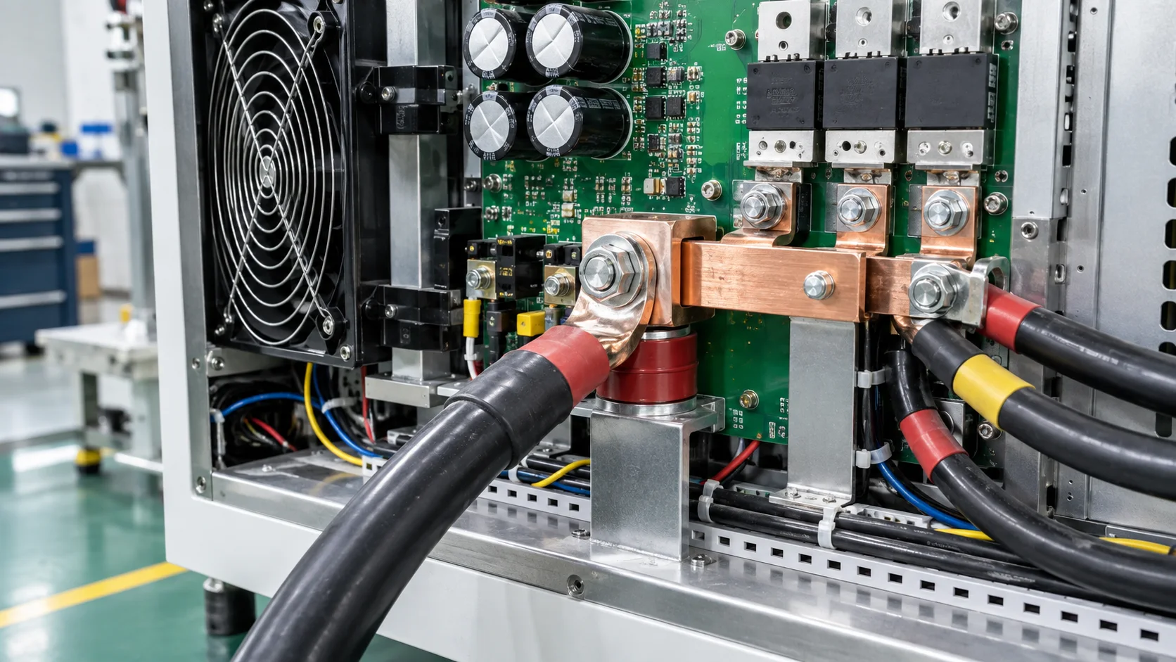
Quick answer: Select a PCB terminal for a CNC spindle drive by checking acceleration and braking pulses, pad exits, cabinet airflow, motor-cable support, vibration, clearance and segmented drop, not motor current alone.
Questions answered on this page
- Why use PCB welding terminals in spindle drives?
- How do braking pulses affect selection?
- How does cable bending reach the solder joint?
- How should pad exits and vias be tested?
- What should production inspection record?
Application context
CNC spindle drives connect a DC bus, inverter modules, brake resistors and motor cables. A PCB welding terminal connects the power board to a bar or heavy cable, while acceleration, deceleration and emergency stops add repeated pulses and vibration. Hongchuan supplies PCB welding terminals matched to waveform, cable, board, copper, direction, temperature, airflow and support.
Four design boundaries
| Boundary | Review | Risk |
|---|---|---|
| Electrical | Continuous, peak, brake pulse and allowed drop | Pad or terminal hot spot |
| Mechanical | Cable mass, bend and cabinet vibration | Joint fatigue |
| Thermal | Airflow, nearby modules and cabinet temperature | Heat accumulation |
| Manufacturing | Pad, stencil, soldering and inspection | Void, offset or poor wetting |
Drop and temperature under brake pulses
Cover low-speed acceleration, high-speed run, deceleration, emergency stop and repeated starts. Measure terminal, solder leg, pad exit, vias, bar joint and cable crimp, and use four-wire segmented drop. If the terminal is cool but the pad exit is hot, inspect copper neck-down, inner layers and via arrays. See pad-exit and via-array validation.
Cable support and solder reliability
Spindle cables are heavy and may flex in a drag chain. Add independent clamps and strain relief so the PCB terminal does not carry all pull. After reflow or wave soldering inspect coverage, verticality, board support, voids and pad edges; use X-ray inspection guidance when needed. Establish resistance and temperature baselines, run the real duty cycle at worst airflow, then repeat after cable motion, vibration and thermal cycling.
FAQ
Is a rating above spindle current sufficient?
No. Brake pulses, pad exit, cable force and cabinet cooling matter as well.
Why can the pad be hot while the terminal is cool?
A copper neck-down, insufficient vias or limited heat spreading can create the local loss.
How should samples be specified?
Provide waveform, cable, board, copper, direction, airflow and support. Start with the welding terminal product page.