


Before interpreting a PCB terminal DC-current offset, establish the zero-current reference, probe magnetic state and instrument configuration. Degaussing addresses residual magnetization; balancing addresses output offset. Do not zero an unknown real DC current away.
Distinguish degaussing from balancing
The Tektronix TCP202 manual explains residual magnetization and remaining output offset. Its current-measurement note discusses warmup and configuration. Use the actual model instructions; controls and preparation conditions differ.
Establish a genuine reference
As an appropriate model-specific procedure permits, check with the probe separated from the test conductor and the jaw closed and locked, away from strong fields. Some instruments permit special in-circuit degaussing conditions, but induced voltage or current can affect the DUT. Do not generalize such exceptions.
Record before and after
Retain model, channel, range, warmup state and zero readings in A. Recheck after overload, strong fields or relevant environmental changes according to the manual. Investigate persistent drift rather than repeatedly hiding it with zeroing. AC coupling cannot replace required DC measurement.
An offset accumulates in integration
A hypothetical constant 0.2 A offset for 5 seconds produces a 1 coulomb integration error. That is not additional charge actually delivered through the terminal. It sets no instrument tolerance; evaluate time-varying drift using the actual record and error budget.
Review records
| Item | Unit or condition | Retain |
|---|---|---|
| Zero reference | Connection and field state | Before/after A |
| Degauss/balance | Model procedure | Time and result |
| Integration | Seconds and coulombs | Offset and processing |
| Events | Overload or changes | Recheck record |
Products and related methods
PCB solder terminals · PCB terminal current measurement: AC/DC probes and pulse limits
Question
Does a zero trace prove zero current? Check offset controls, zeroing, coupling and reference conditions first.
Sources
Tektronix TCP202 degauss and balance;Tektronix current measurement application note
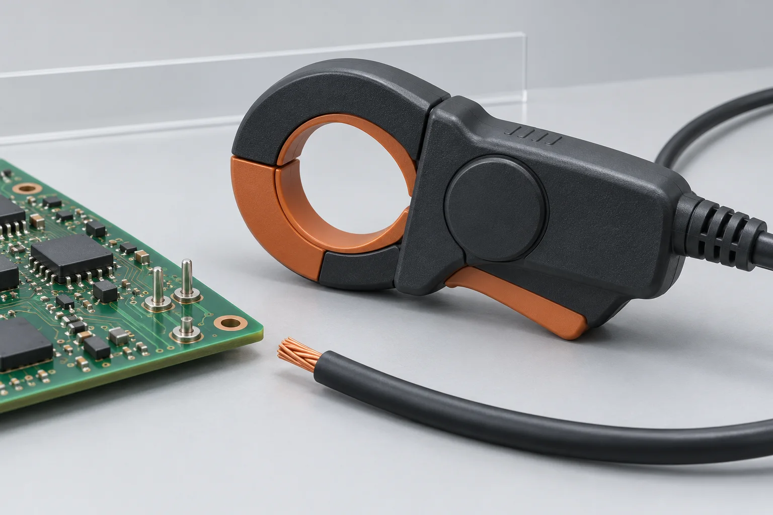
The cover is an AI concept. The probe is separate from the conductor; this is not a measurement or wiring guide. No Hongchuan performance, equipment capability or test result is claimed.