


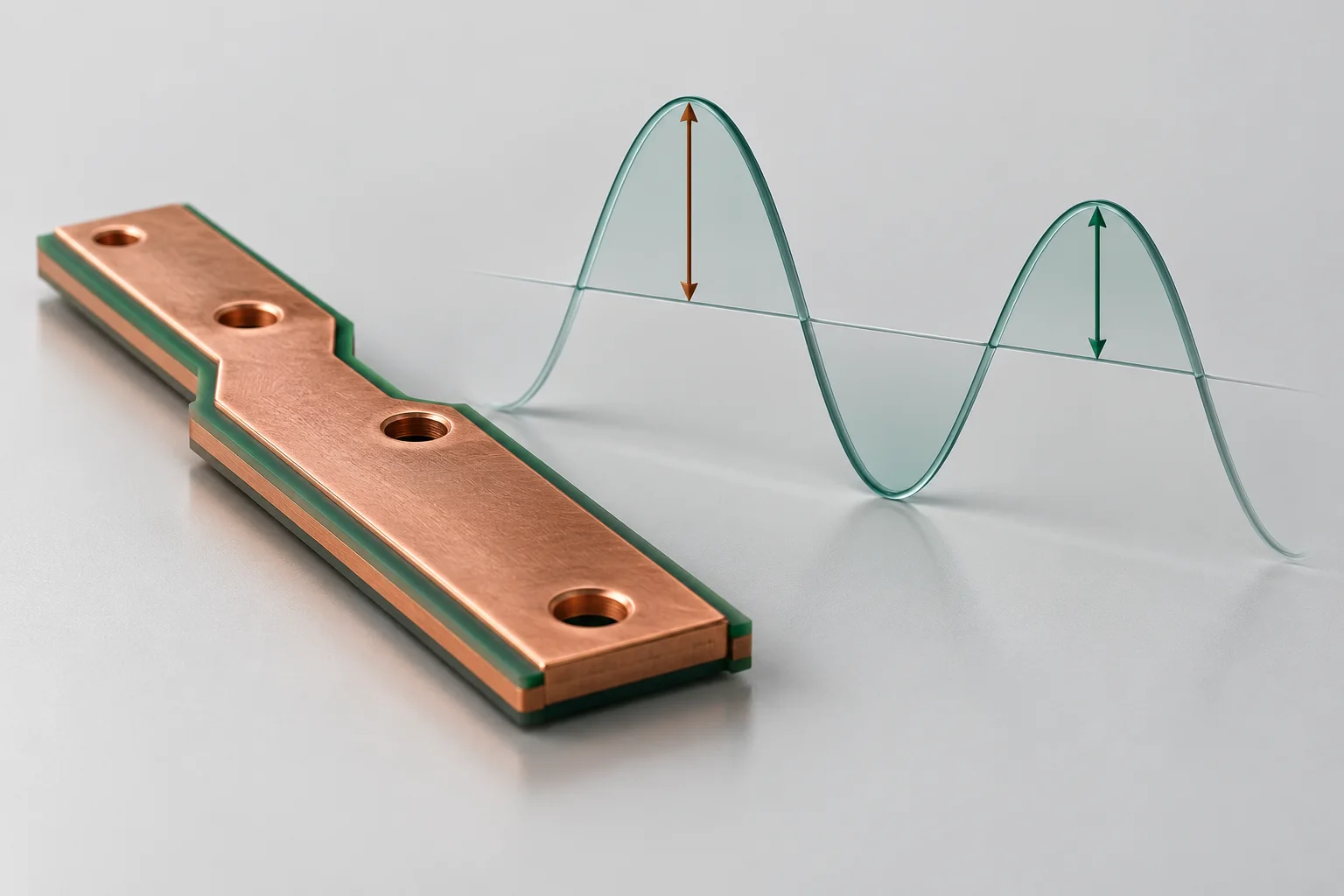
Use the amplitude convention of the actual frequency-domain interface. With peak phasors, a 10 A RMS sinusoid has a peak of about 14.142 A. Do not halve a built-in cycle-average loss again if the normalization is already included.
Confirm the complex-amplitude definition
COMSOL explains reconstructing real time-domain fields from complex phasors. Real and imaginary components jointly determine magnitude and phase. This discussion concerns a linear single-frequency harmonic problem; DC bias, pulses and nonlinear systems need appropriate treatment.
Check a simple resistor first
Assume constant resistance of 1 milliohm and 10 A RMS sinusoidal current. Mean loss is 0.1 W. Under a peak convention, 14.142 A squared times resistance and divided by two gives approximately the same result; incorrectly entering 10 A peak gives 0.05 W. This is not a busbar rating.
Read the loss variable definition
For peak current-density and electric-field phasors, mean Joule heating commonly uses 0.5 Re(J dot conjugate(E)), in W/m3. Verify the actual interface and variable; do not apply another factor to RMS-normalized or already averaged output. A volume integral gives W.
Keep comparison inputs consistent
Archive frequency, source amplitude, normalization, phase and loss-variable name. Check electrical power against the resistive benchmark before evaluating skin, proximity or temperature effects. A normalization change must not be attributed solely to geometry.
Review records
| Item | Unit or condition | Retain |
|---|---|---|
| Source | A, peak or RMS | Interface convention |
| Local heating | W/m3 | Cycle averaging |
| Total loss | W | Integration region and variable |
Products and related methods
PCB SMD copper busbars · Pulsed busbar current explained with RMS and I²t
Question
Must thermal coupling be multiplied by 0.5 manually? Check whether the built-in loss is already averaged under the chosen convention.
Sources
COMSOL frequency-domain amplitude conventions;COMSOL electromagnetic heating workflow
The cover is an AI concept. The waveform and arrows are amplitude concepts, not an exact sinusoid or simulation output. No Hongchuan performance, equipment capability or test result is claimed.