


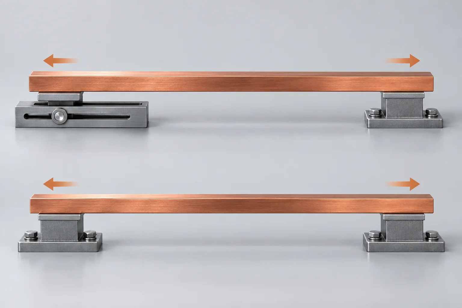
Match thermal-expansion constraints to the actual supports. A uniformly heated free homogeneous body can expand without corresponding restraint stress. Restricting expansion introduces reactions. Numerical stabilization should not unintentionally block physical thermal movement.
Define what fixed means
COMSOL distinguishes global restraint, local boundary restraint and internal rigid connections. Fixing a complete hole boundary may differ from a bolt contact, compliant bracket or permitted sliding interface.
Compare two ideal cases
Assume a uniform 100 mm bar, alpha 17e-6/K and a 50 K rise. Free extension is 0.085 mm. Separately assume uniaxial linear elasticity with fully restrained axial movement and E of 100 GPa: compressive stress magnitude is 85 MPa. The support conditions differ.
Keep the idealization explicit
All properties are hypothetical. Yielding, buckling, gradients and solder joints are excluded. Actual board and fixture stiffness matter. The calculation establishes neither a product acceptance stress nor installation torque.
Account for fixture expansion
COMSOL notes that surroundings represented by constraints may themselves expand. Retain reference temperature, temperature field, permitted directions and fixture-displacement evidence. Explain numerical rigid-motion suppression separately from physical fixing.
Review records
| Item | Unit or condition | Retain |
|---|---|---|
| Fixed boundary | Restricts specified movement | Physical support |
| Sliding boundary | Permits selected movement | Friction and other joints |
| Fixture displacement | mm and reference temperature | Material and temperature |
Products and related methods
PCB SMD copper busbars · Differential Expansion in Copper–Aluminum Connections: Calculate Movement First
Question
Does convergence prove the supports are correct? Compare reactions and displacement directions with the physical assembly.
Sources
COMSOL constraints and thermal expansion;COMSOL structural stability in thermal expansion
The cover is an AI concept. Supports and arrows illustrate constraints, not an installation recommendation or stress result. No Hongchuan performance, equipment capability or test result is claimed.