


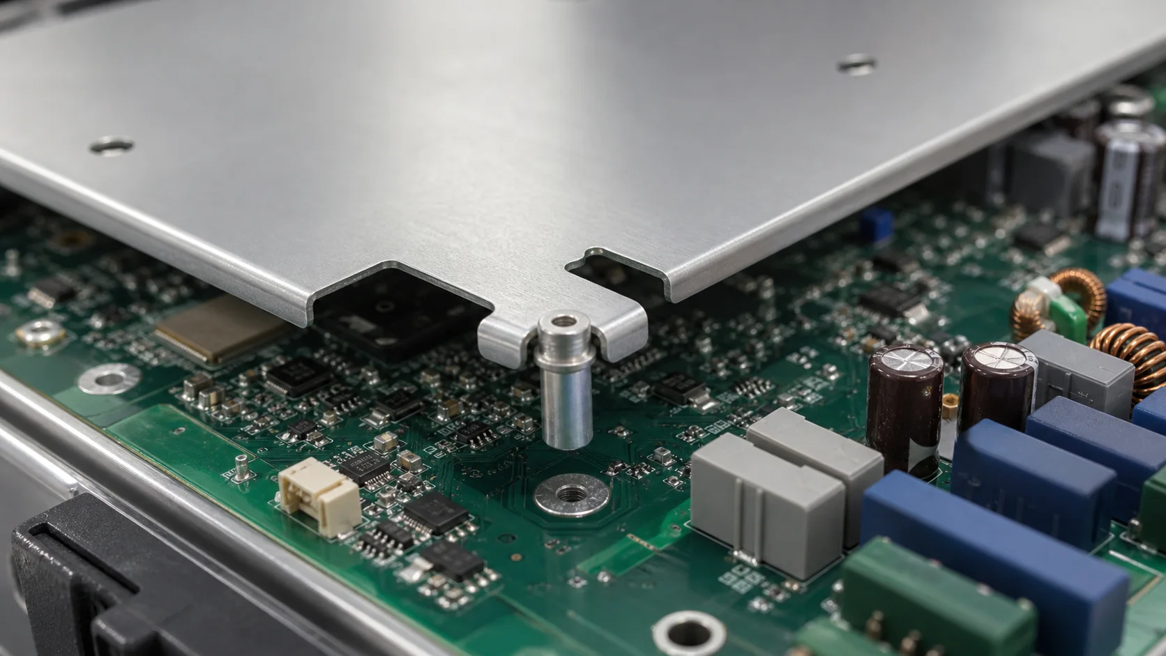
Quick answer: An SMT nut for an inverter EMI shield must retain PCB pull and shear strength after reflow, preserve shield grounding after fastening, and avoid pad lift, annular cracks or thread contamination after service torque and thermal cycling. Review nut height, board thickness, pad, stencil, shield spring, screw and ground point together.
Questions answered on this page
- Why use SMT nuts for inverter EMI shields?
- How can fastening strength and EMI grounding be combined?
- How can thread contamination and pad lift be prevented?
- How should torque match board thickness?
- How should grounding and reliability be verified?
Application context
A metal shield on an inverter control or power board limits coupling from switching nodes, inductors, communications and sensing circuits. The SMT nut goes through SMT and reflow, then a screw attaches the shield or bracket. Hongchuan supplies SMT nuts matched to board thickness, thread, pad and fastening direction.
Separate fastening from grounding
| Function | Key area | Validation |
|---|---|---|
| Fastening | Pad, screw, shield and bracket | Torque, pull and shear |
| Grounding | Shield edge, spring, ground point and copper | DC resistance and continuity |
| Manufacturing | Stencil, paste, placement and reflow | Appearance, X-ray and gauge |
| Reliability | Board thickness, expansion and service cycles | Post-cycle measurements |
The nut pad spreads fastening load, but shield grounding should not depend only on solder. Use a defined ground point, spring or metal-to-ground contact and confirm it by measurement.
Board, pad and thread matching
Board thickness affects bottom support, pad area and bending after fastening. A small pad concentrates edge stress; a large pad can consume HV spacing or routing area. Match nut height to shield, screw length and internal clearance. Control paste around the thread with stencil and volume. See SMT nut pad and torque validation.
Ground continuity and production
After assembly, measure low resistance between the nut, multiple shield locations, spring contacts and PCB ground. Include the far shield edge, not only the nut. Recheck after fastening, thermal cycling and service cycles. Large metal nuts can change local reflow heating and allow solder into the thread, so define paste avoidance, cleaning, visual inspection, thread gauge, pull, torque and grounding sampling.
FAQ
Does a strong solder joint prove reliable shield grounding?
No. Joint strength, nut conductivity, shield contact and PCB ground are separate metrics.
Is higher torque better?
No. Excess torque can lift pads, crack annular rings, bend the board or deform the shield. Set a window for the screw, board and structure.
How should samples be specified?
Provide board thickness, screw, target torque, shield thickness, pad and reflow process. Start with the SMT nut product page.