


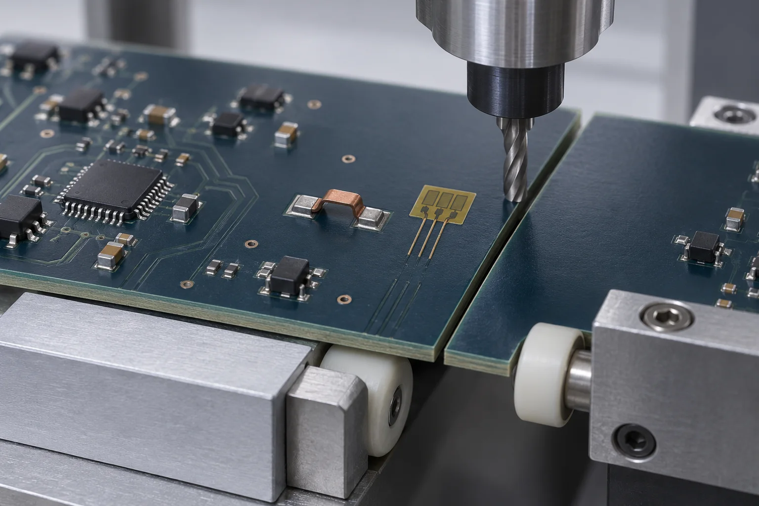
Validate surface mount PCB jumpers after depaneling with local board-strain measurements and joint checks, not board displacement alone. Strain is ε = ΔL/L; 1 με = 10−6. Local PCB strain is not the actual strain inside the jumper or solder. No universal microstrain acceptance limit is asserted for all jumpers.
Millimeters and microstrain describe different things
NI's strain measurement documentation defines strain as fractional length change, positive or negative. For unit conversion only, 300 με = 0.0003 = 0.03%. Center-board deflection in millimeters depends on board dimensions, support and loading. Equal deflections need not produce equal strain beside a joint.
Locate the damaging process step
The public IPC/JEDEC-9704A excerpt describes strain-gauge testing through assembly, testing and handling, including depanelization. This is the 2012 revision A excerpt, focused on specified SMT package applications. It is neither Hongchuan jumper certification nor a transferable jumper strain limit.
| Record | Define | Purpose |
|---|---|---|
| Position and direction | Coordinates relative to pads/cut and gauge axes | Comparable locations |
| Measurement configuration | Gauge, bridge, compensation and sampling | Control drift and capture transient peaks |
| Process state | Board thickness, panel, support and removal sequence | Separate cutting from handling |
| Result | Signed time histories, peaks and applicable strain rate | A peak alone misses event context |
Run a controlled first comparison
Agree feasible gauge positions with assembly and reliability engineers. Avoid materially altering support with the gauge, adhesive or leads. For a rosette, state grid directions, transformations and the reported metric; one-axis strain cannot be compared indiscriminately with principal strain. Record acquisition and filtering that resolve the short process events.
Compare the existing setup with a controlled support arrangement near the cut, using matching board and jumper batches. Mark cutting, clamping and board-removal events. Supports must not push into jumpers, joints or nearby components. Perform agreed visual and electrical checks before and after depaneling; use cross-sectioning or other suitable methods when hidden cracks are a concern. Electrical continuity alone does not demonstrate an undamaged joint.
Specify the actual assembly boundary
Provide panel drawings, depaneling method, board thickness, support, soldered geometry and observed failure information with a PCB jumper enquiry. Agree limits through customer requirements, supplier information and assembly validation, rather than borrowing BGA or ceramic-capacitor values. Also check post-reflow jumper clearance; distinguish bridge span from overall length.
FAQ
Does router depaneling guarantee undamaged joints? No; clamping, support and removal still warrant evaluation.
Is a center-board measurement sufficient? Not necessarily. Choose locations for the actual joint positions and loading.
AI-generated depaneling measurement illustration, not Hongchuan production or test records. The unit example is not an acceptance limit or strain certification.