


UL 94 V-0 for an insulation material near a PCB solder terminal does not replace CTI, creepage assessment or assembly verification. V-0 describes burning behavior of specified specimens; CTI assesses relative tracking resistance. Neither independently establishes the terminal's continuous working voltage.
Identify which material the document covers
UL Solutions' combustion-test description explains that the UL 94 V method examines burning, afterglow and flaming drips. A metal solder terminal is a conductor. This article concerns possible system-level PCB materials, barriers or insulating washers; it does not claim that a Hongchuan terminal includes or certifies those parts.
Connect the document to the actual manufacturer, grade, applicable color and thickness. UL's recognition-field explanation lists minimum thickness, flame class and CTI separately. A purchasing requirement saying only “flame-retardant plastic” needs the actual material and conditions; matching appearance does not justify borrowing another grade's data.
| Record | Describes | Does not independently establish |
|---|---|---|
| UL 94 V-0 or another flame class | Specified specimen burning behavior | CTI or assembly voltage rating |
| CTI | Relative tracking resistance | Continuous safe working voltage |
| Thickness and color coverage | Applicable material-data conditions | Every thickness or material |
| Assembly insulation review | Actual geometry, environment and standards | Release based only on a material name |
A CTI voltage is a test-related index
UL Solutions' IEC 60112 description identifies CTI as a relative tracking-resistance assessment. Its voltage belongs to a particular test method. A reported CTI of 600 does not establish continuous 600 V operation in any PCB arrangement.
V-0 likewise does not determine CTI. Obtain data for the actual material rather than assigning a group from a generic FR-4 or resin name. A replacement can retain the flame class while changing electrical or mechanical properties.
Return to the assembled insulation path
When specifying PCB solder terminals, supply complete terminal and fastener envelopes, PCB layout, working voltage and environmental conditions. The insulation-design owner must determine material groups, pollution conditions, insulation type and distances under the applicable standard. No universal millimeter value is supplied here.
Solder, washers and screws at tolerance extremes can change actual geometry. Terminal center spacing alone is insufficient. Assess air clearance and surface creepage separately; see high-altitude clearance review. Material documents and assembly design should correspond without substituting for each other.
Common questions
Does a supplier's V-0 screenshot certify the complete equipment? Check the document's subject and scope. A material flame class cannot be relabeled as equipment certification.
Can parts with identical CTI be exchanged freely? Temperature, thickness, mechanical and processing requirements still need review through change control.
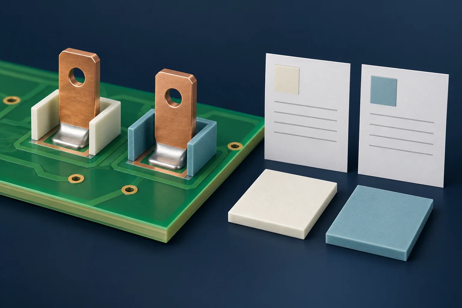
Cover is an AI insulation-material illustration, not Hongchuan photography, testing or certification. This article provides no terminal voltage rating, clearance requirement or compliance determination.