


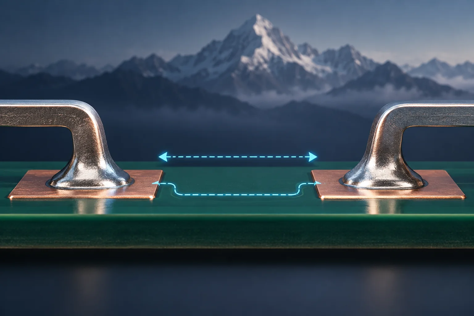
For PCB solder terminals used at altitude, identify the applicable product requirements and maximum operating altitude, then review the shortest air clearance using the prescribed method. Establish the baseline before applying an altitude correction. Creepage follows an insulating surface and requires its own assessment; do not mechanically apply one air-clearance multiplier to every surface distance.
Pin pitch is not minimum air clearance
Terminal center spacing locates the pins. Actual minimum distance also depends on terminal contours, solder protrusions, screws and washers. Locate the shortest air path in the complete three-dimensional assembly across the relevant insulation boundary.
The public scope of IEC 60664-1:2020 covers low-voltage insulation coordination and guidance above 2000 m. The page also lists a consolidated version incorporating Amendment 1:2025. Verify the adopted edition, product standard and scope conditions. This article has not accessed the paid full text and gives no universal voltage-to-distance rule.
Understand a published correction example
TI white paper SLUAAR5, August 2023, illustrates a motor-drive case: a 3 mm baseline at 2000 m multiplied by 1.29 for 4000 m becomes 3.87 mm.
The baseline belongs to that example's established insulation conditions. Do not assign it to an arbitrary terminal voltage. Confirm the multiplier against the project's adopted requirements and edition. This calculation is not a Hongchuan altitude or voltage rating.
| Review item | Confirm | Avoid |
|---|---|---|
| Clearance | Shortest air path, baseline and altitude method | Using center pitch alone |
| Creepage | Surface path, working voltage and material conditions | Automatically applying an air-path multiplier |
| Metal geometry | Terminal, solder and fastener extreme positions | Ignoring washers or protruding screws |
| Environment and requirements | Maximum operating altitude, pollution conditions and edition | Substituting a shipping location for the use boundary |
Check tolerances after determining the requirement
Once required minimum clearance is established, review permitted assembly states. Include shape tolerances, mounting offsets and solder geometry, and identify the limiting path. A nominal spacing above the requirement does not prove compliance at tolerance extremes.
Evaluate creepage on the actual insulating surface. Whether solder mask, coating or slots may be credited depends on the adopted requirements and process evidence. A visible coating alone does not justify arbitrary distance reduction. Plan clearance, creepage and solid-insulation checks for their respective purposes.
Provide the complete application boundary
For a PCB solder terminal enquiry, supply maximum altitude, working voltage, relevant overvoltage conditions, board layout and full fastener contours. System and compliance personnel should establish insulation and environmental requirements. Unverified M3/M4/M6 terminal specifications remain drawing requests, not confirmed high-altitude saleable models.
Altitude-related thermal and current capability also require evaluation. Completing a distance review is not whole-system qualification. See terminal derating-curve checks, and compare the actual environment with test conditions.
FAQ
Does every terminal at 4000 m require 3.87 mm? No. That value belongs to TI's stated example. Establish the project's own baseline first.
Can coating bypass clearance review? Not by assumption; its suitability needs applicable requirements and validation.
AI-generated insulation concept, not to scale and not a Hongchuan product or certified wiring drawing. The published example establishes no product altitude, voltage or certification rating.