


A surface mount PCB jumper thermal-cycling report needs more than a cycle count. Include the actual assembly, temperature limits, measured specimen traces, ramp rates, dwell definition and failure criteria. Chamber air reaching a setpoint does not prove the jumper solder joints have reached it.
Keep chamber and specimen traces separate
ESPEC's rapid-temperature-change equipment description distinguishes air and specimen ramp rates and describes separate specimen sensing. This distinction informs recordkeeping; the equipment's advertised rates are not jumper qualification requirements.
For surface mount PCB jumpers, copper weight, board thickness, fixtures, loading and airflow can affect local response. Keep sensor-location and attachment photographs. Identify whether a trace represents chamber air, the jumper body or a nearby pad. The test owner should approve sensing that does not materially alter the assembly.
Define when dwell starts
Programs can use different timing logic. Report the method actually used rather than relabeling chamber arrival as specimen arrival. Suppose an approved plan requires ten minutes after its specimen-temperature-band criterion is met. Chamber air enters the band at 12:00, but the specified specimen condition is not met until 12:04. If it remains satisfied, the ten-minute period ends at 12:14. This illustrates timing only, not a recommended temperature, band or dwell duration.
| Record | Unit or detail | Comparison enabled |
|---|---|---|
| Extremes and allowed bands | °C; identify air or specimen | Conditions reached |
| Heating and cooling rates | K/min or °C/min and interval | Actual transition speed |
| Dwell and transfer | Minutes, trigger, interruptions | Per-cycle exposure |
| Assembly and checks | Stack-up, solder, fixture, criteria | Applicability to the intended board |
Faster may change the stress
ESPEC Technology Report No. 7 discusses internal-to-surface gradients from rapid changes. It is historical mechanism guidance, not a source of current mandatory conditions. Before increasing speed, verify that the intended failure mechanism remains relevant rather than deciding solely by shorter elapsed test time.
The public IEC 60068-2-14:2023 description covers temperature-change effects on specimens and notes revised reporting requirements. If a contract invokes it, follow the agreed edition and complete requirements. This article does not claim access to the full standard or supply a universal cycle count.
Common questions
Does continued conduction prove crack-free solder? It satisfies only the specified electrical check. Preserve before-and-after inspection and investigate hidden damage where required.
Can a result transfer to another PCB? Reassess changes in stack-up and support. Manufacturing strain is a separate load, discussed in depaneling strain validation.
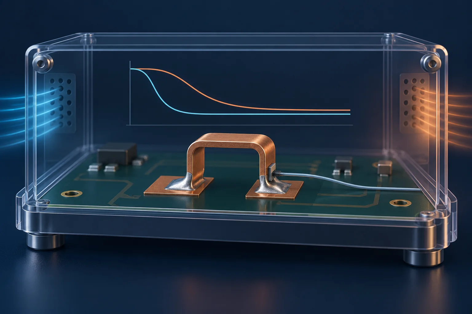
Cover is an AI thermal-cycling illustration, not Hongchuan equipment, measured traces or qualification evidence. The timing example is not a test specification or life commitment.