


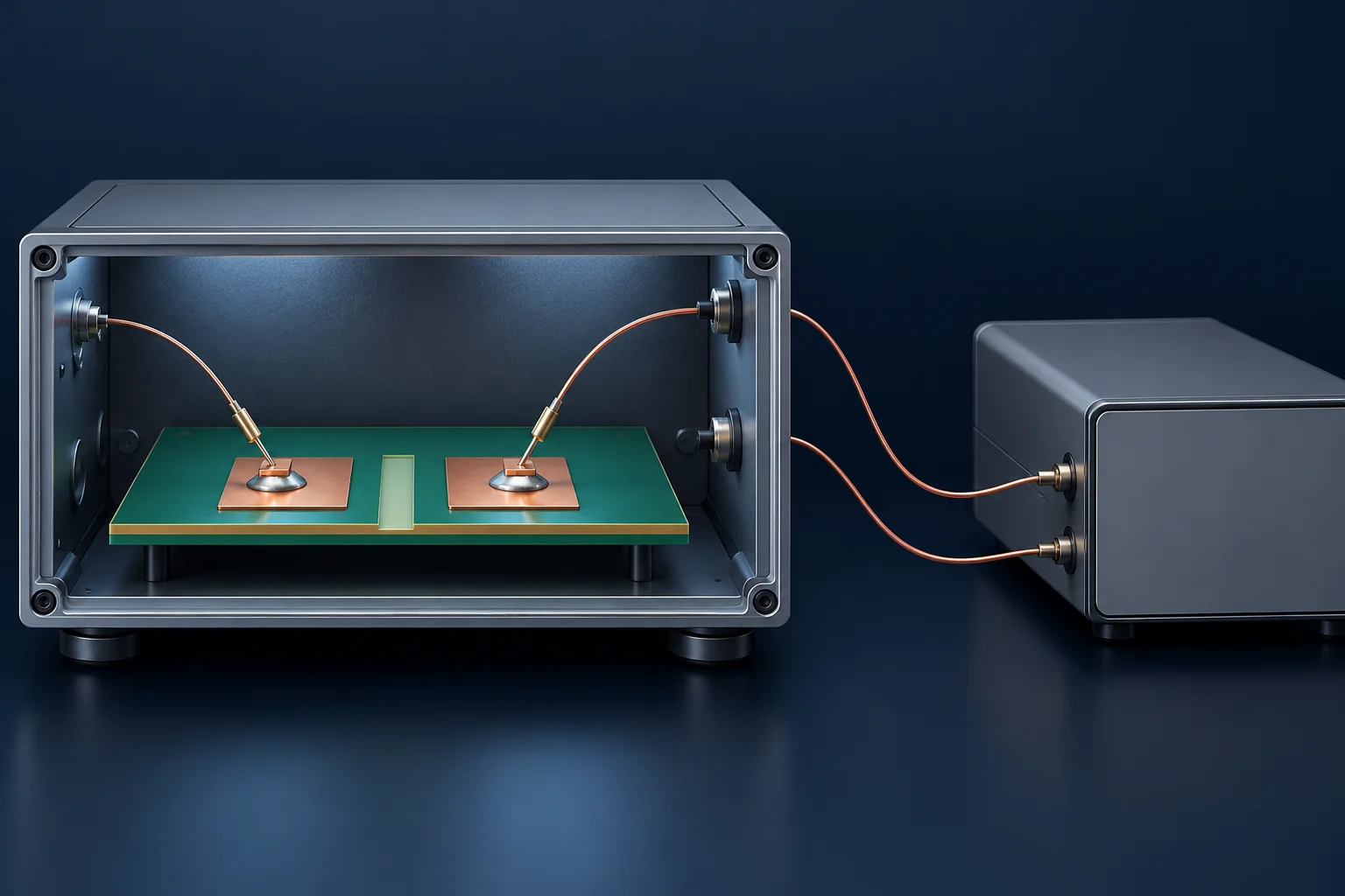
A PCB solder terminal hipot pass does not automatically replace an insulation-resistance report. The tests use different conditions and results. Define the mutually insulated terminals or terminal-to-chassis boundary first. Resistance along one continuous metal terminal is a separate conduction-path measurement.
Separate quantities and units
Associated Research's electrical-safety overview distinguishes dielectric withstand testing from quantitative insulation-resistance measurement. This article uses that distinction, not its example industry voltage formulas, historical standard settings or verification-box wiring values.
| Test | Typical record | Question answered |
|---|---|---|
| Hipot | AC/DC, V or kV, seconds, current, judgment | Withstand under specified conditions |
| Insulation resistance | DC voltage, reading time, MΩ or GΩ | Resistance of an insulation path |
| Continuity or low resistance | Test current, mΩ or μΩ, sensing boundary | Resistance along a metal path |
A metal terminal is normally a conductor. Insulation to another potential depends on the PCB, air, insulators and assembly geometry. Connecting across the same continuous metal piece and expecting high insulation resistance selects the wrong object. Define potential groups and boundaries from the drawing and system insulation design when specifying PCB solder terminals.
Current may not be steady immediately
Chapter 6 of the HIOKI DSM-8104 manual discusses charging, dielectric absorption and leakage, plus the effects of voltage, time and temperature. Preserve ramp, waiting and reading times instead of reporting only the largest displayed resistance.
For a hypothetical specified DC condition, 100 V and a stable resistive current of 1.0 μA give R = V/I = 100 MΩ. This is unit arithmetic, not a recommended test voltage or pass limit. Charging and absorption currents, fixture leakage or connected board components can affect readings; they cannot all be attributed to terminal material.
Review the board configuration before testing
An approved plan should identify potential groups, PCB state, neighboring components, cables, fixtures, temperature, humidity and acceptance criteria. AC hipot current can include a capacitive component. Dividing AC voltage by total measured current does not establish DC insulation resistance, and AC/DC tests cannot be substituted merely through a peak-voltage conversion.
Trained personnel must use suitable protection, interlocks and an approved procedure. The HIOKI manual warns that residual voltage may remain after measurement stops. Follow equipment and specimen requirements for discharge and safe-state confirmation before contact. This article does not provide field high-voltage wiring instructions.
Common questions
Does “no breakdown” establish continuous operation at the test voltage? No. A short-duration test voltage is not a continuous working-voltage rating.
Does high insulation resistance prove good metal contact? These are different paths. See four-wire contact-resistance measurement for the conductive connection.
Cover is an AI insulation-test illustration, not Hongchuan equipment, certification or test evidence. Arithmetic examples are not test conditions, ratings or safety procedures.