


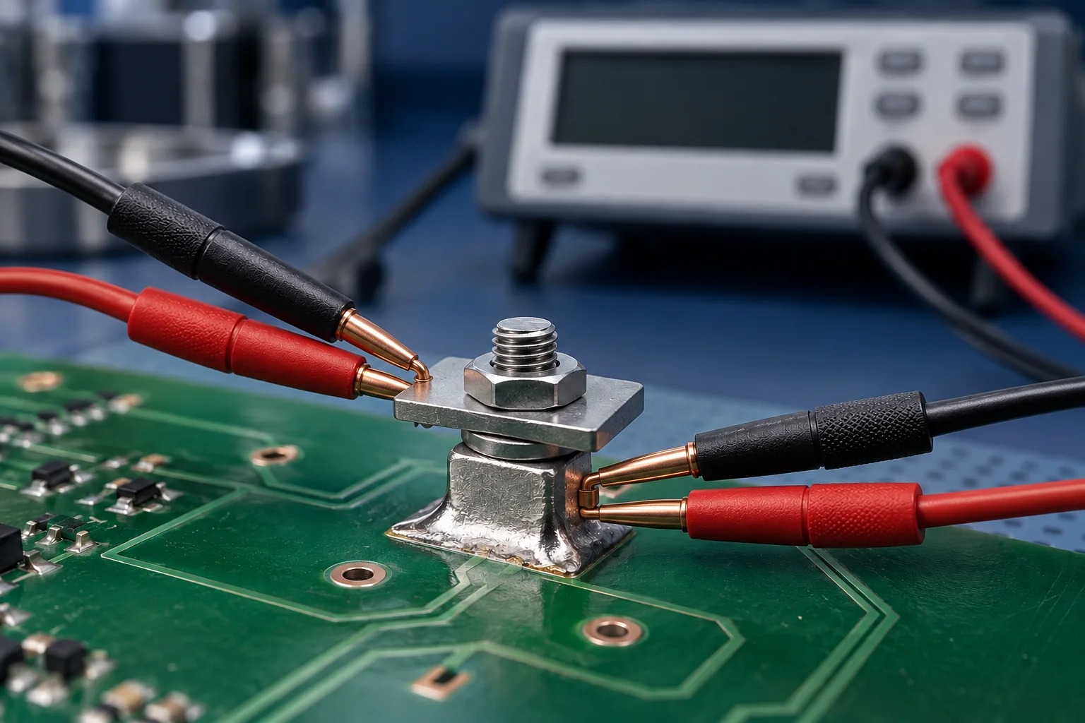
If a separable PCB terminal contact must be evaluated in its original low-level electrical condition, perform the agreed dry-circuit measurement before load tests that may change the contact. A later low reading cannot automatically describe the original surface-film condition. Bulk metal and solder joints require methods matched to their own test objectives.
Identify the interface before selecting the test
A PCB solder terminal assembly can include a bolted lug interface, a mating contact pair, bulk conductor and solder joint. They are different measurement objects. Low-level contact testing does not establish one universal resistance limit for a copper conductor or replace loaded temperature-rise verification.
| Objective | Object | Required context |
|---|---|---|
| Original low-level contact | Specified contact pair or comparable interface | Voltage/current limits and sequence |
| Soldered connection resistance | Joint and conductors inside fixed boundaries | Boundary, temperature and duration |
| Loaded functional test | Actual current and thermal path | Current, environment and temperature locations |
| Post-treatment recheck | Previously loaded or conditioned interface | Treatment history; not an original-state result |
What the 20 mV and 100 mA conditions mean
The publisher's IEC 60512-2-1:2002 preview describes the millivolt-level contact method where required by the detail specification, limiting test voltage to 20 mV and current to 100 mA. Keithley's low-level handbook explains voltage limiting to avoid puncturing contact films and recommends dry-circuit measurement before other electrical tests.
These are test-method conditions, not HC terminal current ratings. Selecting a 100 mA setting alone does not establish compliance: review open-circuit/source voltage limiting, the actual measurement mode and fixture. A standards-based test needs the complete applicable method and an agreed detail specification.
Save actual current as well as the setting
For a hypothetical 0.5 Ω resistance, 100 mA would require 50 mV, exceeding 20 mV. An ideal source limited to 20 mV could supply at most 40 mA into this purely resistive object. This demonstrates the limit relationship, not instrument accuracy or a contact acceptance criterion. Once voltage limiting occurs, do not calculate resistance using the originally requested 100 mA.
As a reporting proposal, save instrument model, mode, source limits, actual current, settling time, sense locations and assembled contact state. Manage offsets and thermal EMFs without raising current beyond the agreed low-level conditions.
State the sequence in the test plan
If an original-state value is required, measure the electrically untreated interface first. Carry out the agreed functional or environmental test and then remeasure under the same stated conditions, identifying the preceding treatment. Specify whether one specimen or separate controls are used. Log cleaning, retightening and contact replacement.
See four-wire terminal measurements for sense boundaries. A result below another supplier's example is not an acceptance decision for a different assembly.
Frequently asked questions
Can a dry-circuit reading after a high-current test recover the original value?No. It records the treated condition. Use an untreated specimen if the plan requires original-state evidence.
Must every PCB solder terminal undergo this test?This article establishes no blanket requirement. Applicability depends on the interface, use and detailed specification.
Cover image is an AI-generated engineering illustration, not an HC product photograph, laboratory or test record. Hypothetical values are not product specifications or acceptance commitments.