


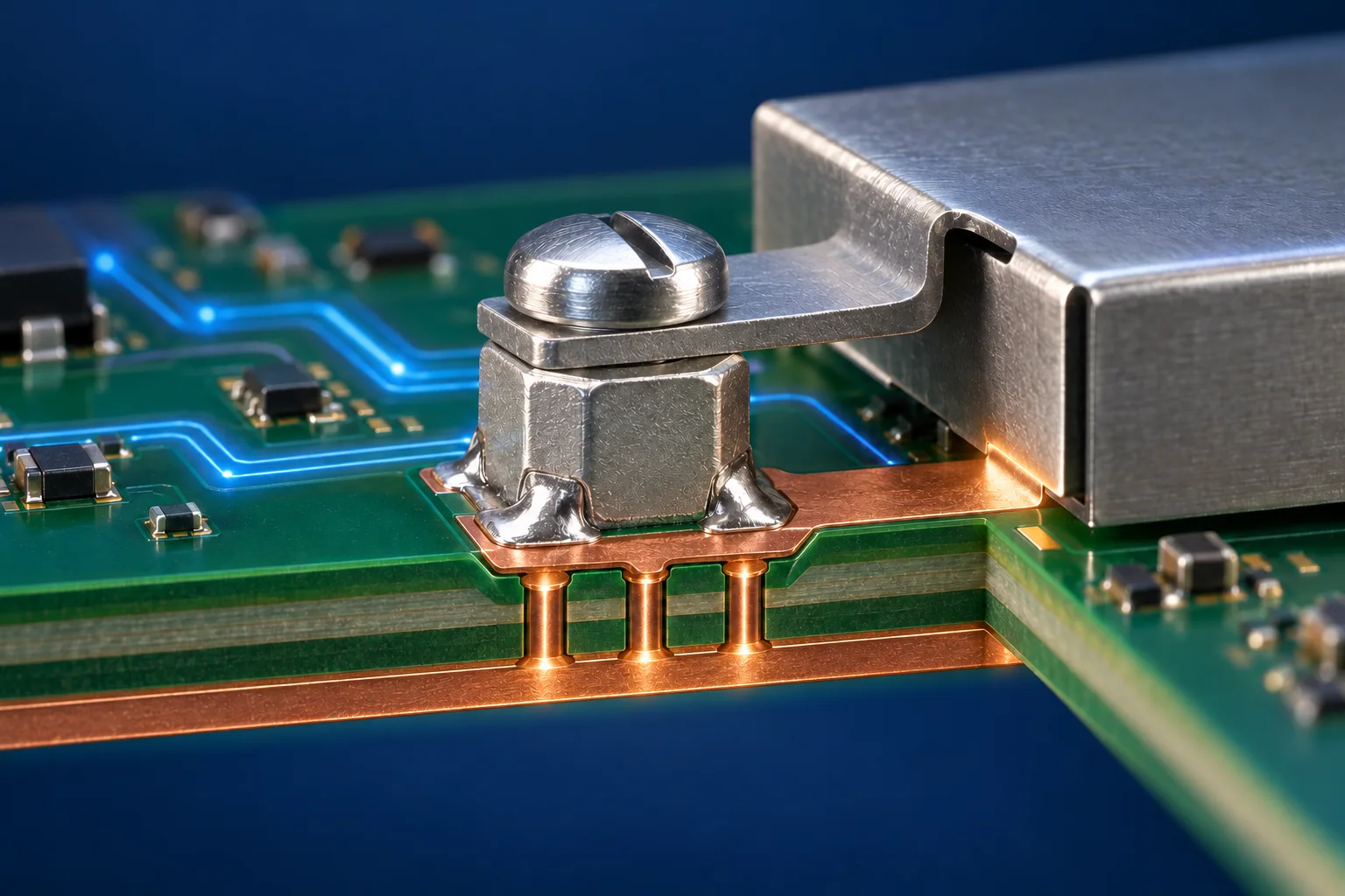
Low DC resistance through an SMT nut grounding assembly describes the connection only between the stated DC test points. RF behaviour also depends on parasitic inductance, contact geometry and PCB return layout. Define the target frequency band and evaluate the full shield-to-ground path; continuity beeps do not verify RF or system EMI performance.
Map the actual current path
With an SMT nut securing a metal shield, trace the shield contact region, clamped interface or screw, nut, solder joint, pad, vias and intended ground plane. If the screw only supplies clamping force and current crosses the shield-to-nut face, record that path rather than assuming all current travels through the thread.
Würth Elektronik's grounding overview calls for a deliberately designed low-impedance PCB-to-chassis path. This principle does not qualify every nut for every frequency. Keep circuit reference, chassis and protective earth roles distinct; protective bonding requires its own applicable safety review.
| Object | DC evidence | Additional review |
|---|---|---|
| Metal contact | Resistance in a stated assembled condition | Coating, pressure and remating |
| Nut and solder joint | Drop across fixed test boundaries | Actual assembly and mechanical state |
| Pad to plane | Continuity and path resistance | Neck-downs, vias and return geometry |
| Complete shield | Selected node connections | Seams, target frequencies and system EMI |
A 10 nH example at two frequencies
Analog Devices' grounding primer explains that a ground conductor has resistance and inductance. Consider a hypothetical series R-L path, not a nut specification: L = 10 nH gives XL = 2πfL, approximately 0.063 Ω at 1 MHz and 6.28 Ω at 100 MHz. Even a hypothetical DC resistance of 1 mΩ would not establish low impedance at those frequencies.
Real assemblies can also exhibit capacitance, mutual coupling and resonance. Do not extrapolate this model across all frequencies or use it as a shielding attenuation result. Record the measurement frequency, ports, fixture and de-embedding method; a long probe loop can include fixture behaviour in the reading.
Keep DC and RF evidence linked to one assembly revision
As a prototype review proposal, maintain one record for DC resistance with fixed points, tightening conditions, surface state and remating count. Keep a second for the target-band impedance or system EMI results, with shield, contact and cable-layout photos. If DC remains stable while EMI fails, investigate the contact and return path plus shield seams before increasing tightening torque.
Mechanical results remain separate. See torque-out versus assembly tightening torque. Neither mechanical strength nor DC resistance alone qualifies the RF path.
Frequently asked questions
Will adding nuts always improve EMI?No. Placement and current-return geometry matter. Compare the actual assembled configurations.
Does thread size define grounding impedance?No. Contact area, surface, soldering, PCB layout and operating frequency are also needed.
Cover image is an AI-generated engineering illustration, not an HC product photograph, laboratory or test record. Hypothetical values are not product specifications or acceptance commitments.