


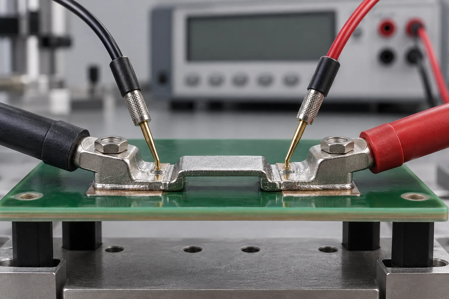
Direct answer Force a known current through two leads and measure voltage with a separate sense pair. Calculate R = V/I. The sense points define the measured resistance. If they span a terminal, solder joint and PCB copper, report the total resistance of that segment.
This guide draws on the Keithley low-level handbook and Keysight low-resistance guidance. Kelvin sensing reduces lead-related error; thermal offsets, self-heating and probe position still matter.
Define the measurement boundary
For a PCB terminal, put voltage probes on opposite sides of the connection of interest. Keep their distance from the interface documented. A bolted joint measurement includes any conductor between the sense points. A solder comparison requires repeatable points on the terminal foot and receiving copper.
| Purpose | Sense span | Report |
|---|---|---|
| Whole power path | Cable lug to PCB copper | Total segment resistance |
| Bolted interface | Fixed points on each side | Joint plus adjacent conductor |
| Solder batch comparison | Identical foot and pad points | Change within a fixed boundary |
A calculated example
These are illustrative inputs, not product test data. A 100 μΩ segment at 10 A produces 1 mV. A constant 10 μV offset creates a 1 μΩ error, or 1%. Higher current improves signal level but increases I²R heating.
Control offsets and repeatability
For an isolated sample that permits bidirectional current, an instrument-supported reversal method gives R = (Vpositive − Vnegative)/(2I), provided current magnitudes match and thermal offset remains stable. Populated boards may have parallel paths and reverse-current limits. Record probe photographs, current, dwell, sample temperature and assembly torque. Use the terminal hot-spot guide to investigate a high-resistance segment.
Common questions
Does a continuity beep prove a good power connection?
No. It cannot replace low-resistance and loaded temperature checks.
Can another terminal's limit be reused?
Only after geometry, materials and measurement conditions are aligned. Agree part-specific criteria against confirmed drawings.
Sources
The cover is an AI-generated concept illustration, not a product photograph or test record.