


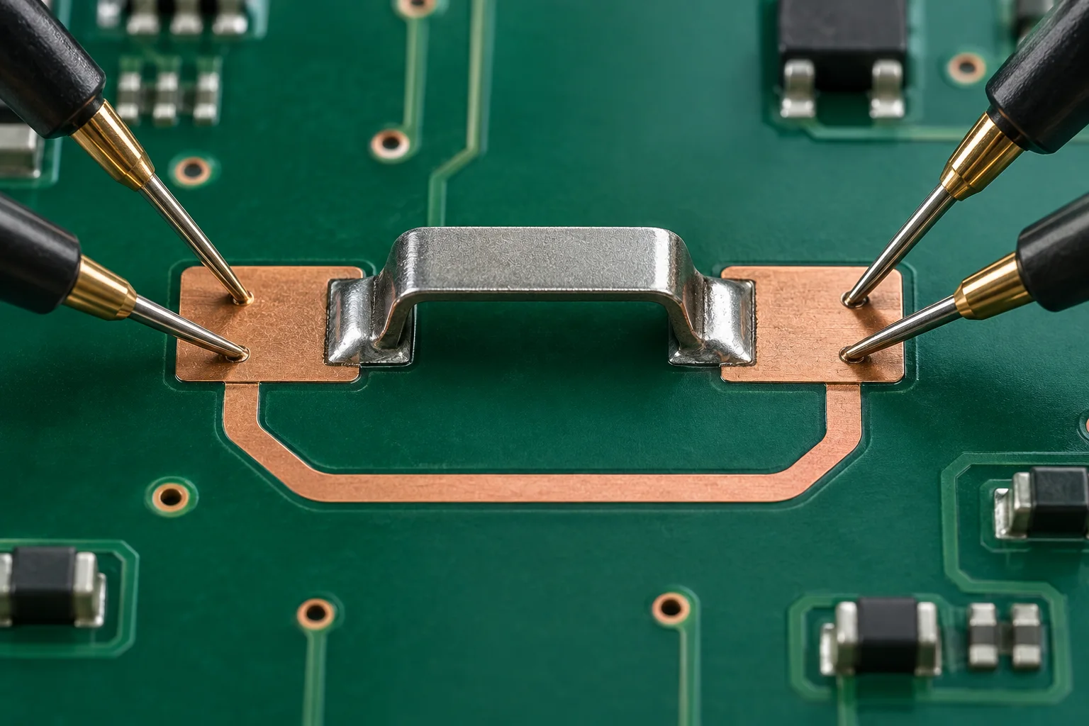
Four-wire sensing does not remove PCB paths in parallel with a surface mount jumper. When the source current splits, voltage divided by total source current yields node-to-node equivalent resistance. To report one jumper path, establish safe isolation or a defined branch-current measurement method.
Review every connection between the test nodes
Fluke's resistance-measurement guide warns about parallel paths in assembled circuits. Around surface mount PCB jumpers, check same-net copper, another jumper, attached harnesses and chassis connections. Follow the board's safety procedure to remove power, isolate supplies and verify stored energy has discharged before using a resistance function.
Keithley's two-wire/four-wire comparison describes separate current and voltage-sense leads to reduce lead-resistance error. Sense wiring does not disconnect other conductive PCB branches.
| Condition | Meaning of the result | Individual jumper value? |
|---|---|---|
| Isolated specimen | Resistance inside the defined sense boundary | State included conductor segments |
| Board without bypass | Jumper, joints and conductors between points | Define the full boundary |
| Passive parallel path present | Equivalent node-to-node resistance | No |
| Semiconductors or stored energy present | May depend on voltage, polarity and time | Do not assume a linear parallel network |
Why an unexpectedly low value may be misleading
Consider a hypothetical passive, linear and stable network. A jumper path Rj = 50 μΩ is parallel to a bypass Rb = 100 μΩ between the same nodes. Req = Rj × Rb / (Rj + Rb) gives approximately 33.3 μΩ. At a total source current of 1 A, the node voltage is about 33.3 μV, not 50 μV.
Ideal four-wire sensing would still return that equivalent value. If the jumper opens, the 100 μΩ bypass remains. Continuity may therefore persist despite an open jumper. A low resistance or beep alone cannot establish that its solder joints are sound.
Choose a board-safe isolation method
As a review procedure, mark the source nodes, sense nodes and all return branches on the schematic and layout. Look for a removable harness or a designed test disconnect. Do not cut copper, lift a soldered part or apply reverse current solely to obtain a reading without an approved board-level procedure. If safe isolation is unavailable, label the result as equivalent resistance between named nodes.
For individual joint evaluation, use a confirmed test coupon or controlled branch-current method with fixed temperature, source current and sense boundaries. Kelvin wiring and low-resistance error checks address other measurement effects but cannot remove topology-driven current division.
Frequently asked questions
Does polarity dependence prove a bypass?No. Thermal offsets, semiconductors and circuit state can also affect the reading; investigate the actual network.
Can the jumper value be calculated from a known bypass?Only if the two-linear-branch model and bypass value are valid. Close resistance values can amplify uncertainty in the inverse calculation.
Cover image is an AI-generated engineering illustration, not an HC product photograph, laboratory or test record. Hypothetical values are not product specifications or acceptance commitments.