


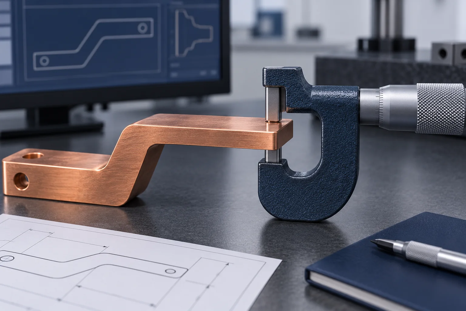
For a PCB busbar dimension near its tolerance limit, review the measured value, expanded uncertainty and agreed decision rule together. Display resolution is not measurement uncertainty. Agree any guard band before inspection and retain the original drawing tolerance.
Separate the specification from the acceptance rule
ILAC-G8:09/2019 distinguishes specification and acceptance limits and explains simple acceptance and guard-banded decisions. Its method can inform a dimensional inspection agreement; this reference is not a statement that HC holds laboratory accreditation.
| Item | Record | Avoid |
|---|---|---|
| Specification | For example, overall width 10.00 ± 0.05 mm | Treating a guard band as a drawing revision |
| Measured value y | Actual reading, location and method | Saving only rounded values |
| Expanded uncertainty U | Units, coverage factor and evaluation | Using display resolution as U |
| Decision rule | Agreed acceptance limits | Changing the rule between batches |
A worked example in millimetres
These are hypothetical values, not HC specifications. The permitted overall width is 9.95 to 10.05 mm. A result y = 10.04 mm has U = 0.02 mm. Under agreed simple acceptance, the reading is within the specification. If a U-sized guard band is agreed on both sides, the acceptance interval becomes 9.97 to 10.03 mm and the reading does not meet that acceptance rule. This does not prove that the true width must be out of tolerance.
NIST explains expanded uncertainty as U = k × uc. Approximate 95% coverage for k = 2 depends on a normal distribution and a reliable standard deviation estimate. The example guard band is an option for discussion, not a universal requirement for copper busbars.
Keep the measurand unchanged during a recheck
Define whether the drawing controls developed width, projected width after bending or the span between mounting points. Span and overall length are different. Specify whether thickness includes plating and whether burrs are excluded. Save temperature, measuring force, support, measurement locations and original readings before re-fixturing. Do not select only the most favourable repeated result.
For SMD busbars, attach the rule to the first-article dimensional report. Follow the agreed recheck or hold procedure for borderline parts. Reducing U requires evaluating the measurement process, not merely displaying more decimal places.
Questions to resolve with the inspection provider
Does a calibration certificate establish process uncertainty?It supplies relevant instrument information, but the actual method, repeatability, environment and part condition still need consideration.
Should every application use a larger guard band?No. It changes the acceptance interval and trade-off between decision risks. Select the rule against function, measurement capability and the agreed specification; do not promise zero errors.
Cover image is an AI-generated engineering illustration, not an HC product photograph, laboratory or test record. Hypothetical values are not product specifications or acceptance commitments.