


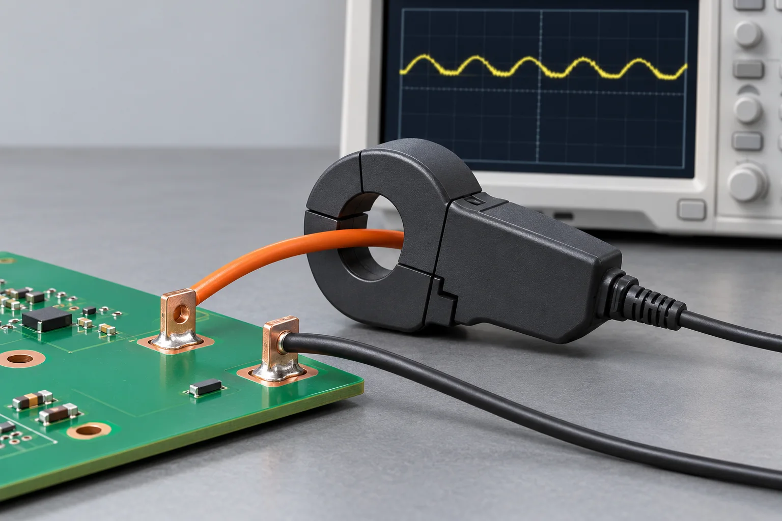
To capture the complete current waveform in a PCB solder terminal test, first establish whether the probe supports DC. An AC-only probe cannot report sustained DC. An AC/DC probe still needs appropriate frequency response, range, RMS and pulse limits, and output scaling. Before interpreting clipped peaks as circuit current limiting, rule out measurement-system overload.
Ripple does not remove the DC component
HIOKI distinguishes winding, Hall and Rogowski sensing methods. Tektronix's probe primer discusses low-frequency limits of AC probes and adding Hall sensing for DC. These principles guide selection; no sensing principle automatically satisfies every current range or accuracy requirement.
As an example, consider 20 A DC plus a sinusoidal ripple with a 5 A peak. A suitable AC chain can observe the ripple, but that trace alone does not recover the 20 A baseline. These values are not a Hongchuan terminal rating.
| Type | Check | Boundary |
|---|---|---|
| AC-only transformer-type probe | Low/high frequency limits, peaks and loading | No sustained DC measurement |
| AC/DC probe with DC sensing | Actual frequency range, current range and zero state | Not unlimited current or bandwidth |
| Rogowski measurement chain | Integrator, frequency range and input limits | No sustained DC; electronics can still overload |
Read limits with time and frequency
Tektronix's AC/DC probe datasheet lists RMS current, pulse peak, frequency derating and amp-second limits separately. They concern different conditions. Do not use the largest current number as proof that an entire waveform is measurable; read the actual model, range and connected-system specifications.
For applicable magnetic-core pulse measurements, amp-seconds relate to the linear range of the core. A hypothetical rectangular 20 A pulse lasting 200 μs has an area of 4000 A·μs, or 0.004 A·s. Whether it can be measured still depends on the probe. This quantity is different from I²t, whose units are A²·s.
Apply the scale factor once
Assume an effective conversion of 100 mV/A, or 0.100 V/A, under valid range, termination and calibration conditions. A raw scope voltage of 2.00 V corresponds to 20.0 A. If the instrument has already identified the probe and displays amperes, do not apply the voltage-to-current factor again.
Retain output mode, scaling, termination and display units. Follow the specific equipment instructions for degaussing, zero adjustment and warm-up. Preserve original traces and status after a setting change or overload indication, then review the measurement chain before diagnosing the circuit.
Keep the terminal test reproducible
For PCB solder terminals, record probe and scope models, ranges, frequency limits, acquisition settings, measurement location and connection state. Assess the complete chain under both instruments' specifications. Voltage-category and insulation requirements also need to match the work, with safe setup by qualified personnel.
The capacitive-load startup guide explains why short current peaks can arise. This page addresses capturing them correctly, not assigning a terminal rating from an attractive trace.
Questions
Does an MHz upper bandwidth guarantee DC response? Check the lower limit and AC/DC specification too.
Does a flat peak prove current stopped increasing? Saturation, overload and bandwidth limitations can also distort the trace.
Sources
HIOKI current-sensing principles; Tektronix probe principles and current limits; Tektronix example of separate RMS, pulse and amp-second specifications.
The AI cover is a conceptual measurement illustration, not a Hongchuan test or wiring procedure. Example currents, durations and scale factors are not terminal or instrument ratings.