


Before calculating PCB terminal power from oscilloscope traces, assess relative voltage/current path delay and multiply the terminal voltage drop by the corresponding current at the same instant. Deskew corrects measurement-path delay; do not arbitrarily align DUT peaks. Define whether the measurement concerns a terminal segment or total supply output.
Define where voltage is measured
Tektronix explains that probes have different propagation delays and instantaneous power uses sample-by-sample voltage-current multiplication. For a terminal segment, use the drop delta-v between defined points and the current through that segment. Bus voltage times current describes a different power boundary.
| Record | Unit or content | Purpose |
|---|---|---|
| Voltage points and current direction | Connection sketch and polarity | Define the evaluated segment |
| Relative delay and correction | ns or microseconds, with sign | Pair samples on a common reference |
| Probe and channel | Model, range and bandwidth | Retain the actual signal path |
| Calculation interval | Seconds, milliseconds or cycles | Reproduce averaging or integration |
| Output | W or J | Separate power from energy |
Use a common reference and preserve real phase
Keysight describes driving voltage and current probes with a common pulse reference for deskew. Tektronix distinguishes nominal propagation-delay compensation from finer fixture-based alignment. Use instructions for compatible instruments and accessories; a published delay from another setup is not your correction.
A DUT may have real dynamic phase relationships. Moving its voltage trace until current peaks match can remove physical information. Keep reference-based correction evidence, then measure the DUT. Recheck after relevant hardware or setting changes as the equipment guidance requires.
Multiply samples before averaging
Consider a hypothetical resistive element during two equal intervals: 20 mV at 10 A and 40 mV at 20 A. Powers are 0.2 W and 0.8 W, averaging 0.5 W. Multiplying the mean 30 mV by the mean 15 A instead gives 0.45 W.
The example excludes transitions and is not Hongchuan test data. For a real dynamic segment, instantaneous delta-v times current can include changing electromagnetic stored energy. State the settled, periodic or other analysis boundary before interpreting electrical power as dissipative heating.
Retain other millivolt-measurement checks
For PCB solder terminals, deskew does not repair overload, offset or unsuitable common-mode conditions. Keep original traces and processing settings, and use equipment ratings and an approved connection plan. Review startup sampling and aliasing separately.
Questions
Are two channels on one scope automatically sufficient? Assess the complete probe paths and actual configuration.
Is there a universal nanosecond limit for steady DC? Judge timing contribution against signal changes and the measurement error budget.
Sources
Tektronix current-probe and power measurement note;Tektronix propagation delay and deskew guidance;Keysight common-reference deskew fixture
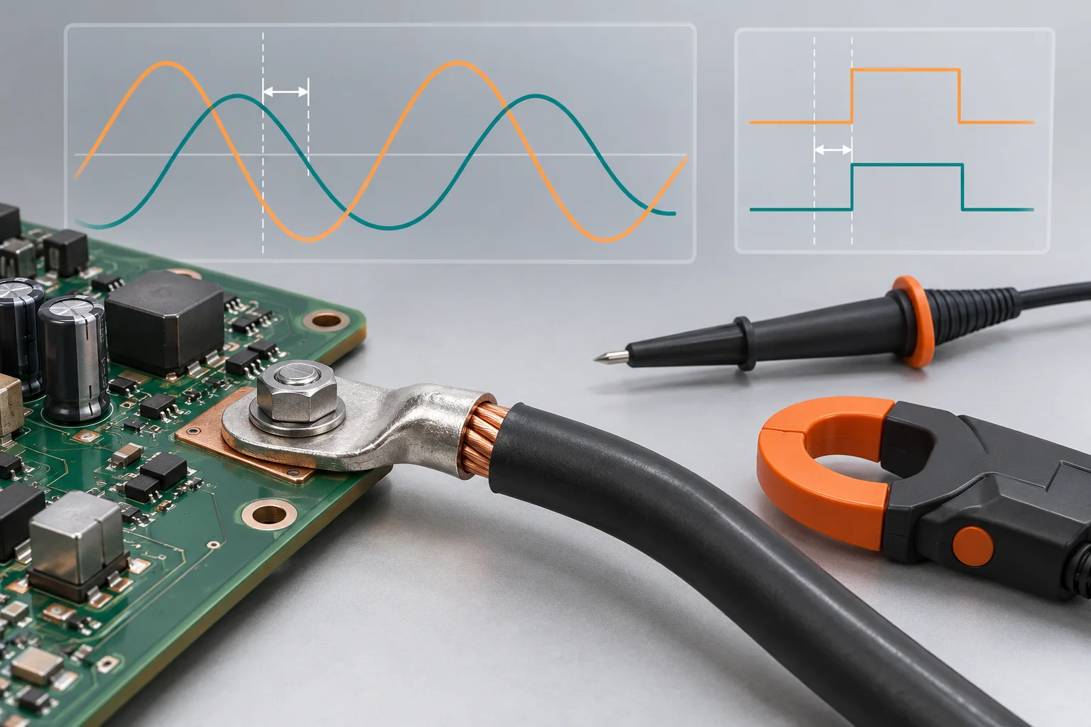
The cover is an AI timing concept with disconnected probes and illustrative traces. It shows no measured Hongchuan loss, equipment capability or accuracy claim.