


For one cylindrical bend in a PCB copper busbar, add the two straight lengths outside the bend tangencies to the bend allowance. In a linear K-factor model, BA=θ(R+Kt), with θ in radians, R the inside radius and t the thickness. Overall flange dimensions extending to virtual intersections are not automatically tangent straight lengths.
Define dimension origins first
The Autodesk Inventor unfold-rule reference gives the linear equation and distinguishes angle-reference options. Mark the arc-to-line tangencies in a section drawing before defining legs, radius and angle.
K is the neutral-axis offset from the inside surface divided by thickness. It is dimensionless. Do not enter an outside radius as R or assign millimeters to K. Here θ means the rotation from the flat condition; confirm conversion and software settings if a drawing instead specifies an included opening angle.
| Input | Definition here | Potential confusion |
|---|---|---|
| L₁ and L₂ | Ends to bend tangencies | Overall legs measured to virtual intersections |
| R | Finished inside radius | Outside radius or nominal tool dimension |
| θ | Bend rotation | Degrees, radians and included angle |
| K | Neutral-axis offset divided by thickness | Software default treated as a material constant |
A method-only example
Assume L₁=10 mm, L₂=20 mm, R=2 mm, t=1 mm, rotation 90° and K=0.40. With θ=π/2, BA=(π/2)×(2+0.40×1)≈3.77 mm. Total flat length is approximately 10+20+3.77=33.77 mm.
K=0.40 is an assumed input, not a universal copper recommendation. The result excludes trim allowance and is not a Hongchuan production blank dimension. If 10 and 20 describe overall outside flanges, use the matching geometric method instead of double-counting bend material.
Validate the unfold rule with production-relevant samples
Autodesk's bend-table guidance relates tables to thickness, radius and angle and identifies measured samples as important inputs. Agree one unfold-rule revision and validate it using relevant material, equipment and operations.
Keep starting length, thickness, temper, rolling direction, final radius and angle, and straight-section references. Adjusting K addresses an unfolding model. Unloaded springback and outer-surface cracking need separate checks; matching flat length does not establish complete forming quality.
State which drawing controls acceptance
For a formed PCB copper busbar inquiry, identify functional dimensions, controlled model, flat-pattern revision and document precedence. Mark a reference-only flat pattern accordingly. Do not silently alter blank dimensions under an unchanged revision.
This simplified method does not cover coined thinning, complex surfaces or interacting forming regions. See copper temper, bend radius and rolling direction for the independent formability review.
Questions
Is flat length the sum of two outside edges? Confirm references and bend-zone definitions before adding dimensions.
Can a previous K value survive a temper change? Recheck its documented scope and validate the actual process.
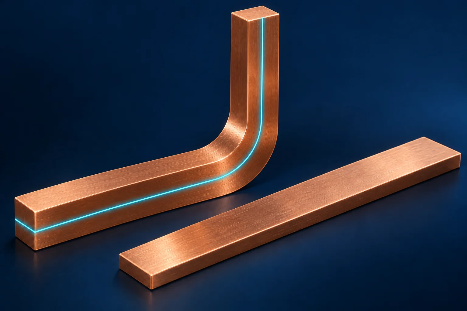
The AI-generated cover illustrates bending and a neutral-axis concept, not a Hongchuan production drawing. Examples are not recommended K values or manufacturing capability claims.