


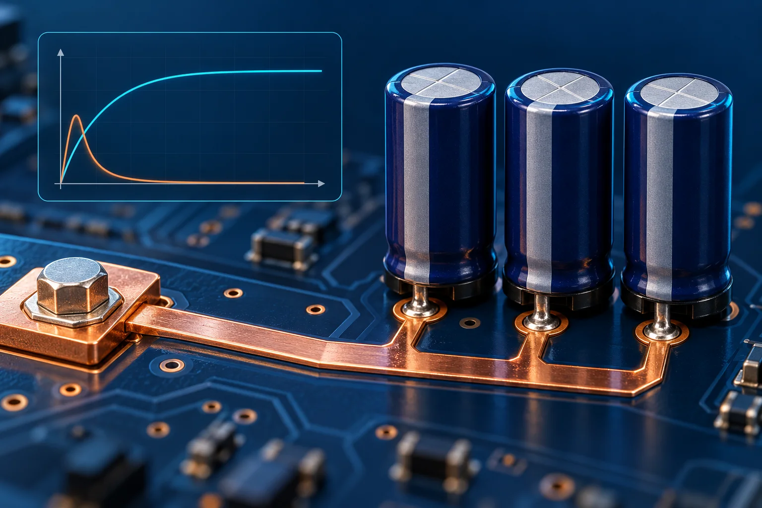
For a PCB solder terminal feeding a capacitive load, assess the startup waveform separately from continuous current. An ideal constant capacitance follows i=C·dV/dt: a faster voltage ramp requires more charging current. A continuous-current capability does not establish permission for energized connection, hot plugging or switch duty.
Use the voltage across the actual capacitance
Texas Instruments' inrush guidance relates capacitor charging current to voltage slew rate. The relevant waveform is the voltage experienced by the load capacitance, not a supply-panel setting or a software waiting period.
Assume constant C=1000 μF=0.001 F and a linear ramp from 0 to 24 V in 10 ms=0.010 s. Ideal capacitor current is 0.001×24/0.010=2.4 A. Any simultaneously operating load adds to current through the terminal path. This is not a terminal rating or a prediction of the peak from directly connecting a supply.
Average charging current is not measured peak current
For constant C, CΔV/Δt gives average capacitor current over the voltage change. It equals a constant ideal current only for a constant slope. Supply limiting, circuit impedance, controls and ringing can alter the actual waveform. Preserve peak, duration and restart spacing rather than substituting one average.
| Item | Record | Not replaced |
|---|---|---|
| Steady operation | Current, ambient and temperature-rise conditions | Startup peak and waveform |
| Voltage ramp | Capacitor start/end voltage, time and trace | Panel setting or software delay |
| Startup current | Peak, trace, position and bandwidth | Average current alone |
| Repetition | Cycles, intervals and initial capacitor state | One cold startup |
| Connection function | Fixed conduction or verified switching device | Switching duty inferred from current rating |
Keep stored energy as a separate quantity
OpenStax's capacitor-energy explanation gives ideal stored energy E=CV²/2. The 1000 μF, 24 V example stores 0.288 J. This is not automatically heat deposited in the terminal joint and does not establish touch safety or safe work after power removal.
Record initial voltage, actual capacitance and circuit state. For voltage-dependent capacitance, confirm the operating-condition value. Follow approved isolation and stored-energy verification procedures before inspection. This guide does not provide discharge-resistor selection, live connection or high-voltage test instructions.
Communicate startup requirements to the supplier
For PCB solder terminals, provide supply range, load capacitance, startup control, measured voltage/current traces, repetition, board thickness and soldering structure. System designers must determine whether limiting, precharge or a dedicated switching device is required, then validate the actual assembly.
Record probe, range, bandwidth, sampling and trigger configuration. Probe saturation or a short record window can conceal peaks. Review the independent steady-state boundary using terminal current-temperature derating conditions.
Questions
Does doubled capacitance double the peak? It doubles ideal charging current at the same voltage slope; real peaks also depend on supply and circuit behavior.
Does a secure screw joint permit energized connection? Follow equipment instructions and the connection device's verified function. A fixed joint is not automatically a switch.
The AI-generated cover and curves are conceptual, not measured data. Examples are not Hongchuan voltage, current, switching or safety ratings.