


A surface mount PCB jumper that remains continuous after vibration is continuous at the time checked. Establishing whether an intermittent open occurred during the test requires monitoring against an agreed electrical threshold and minimum duration, with demonstrated detection capability. One final multimeter reading cannot establish uninterrupted continuity throughout the exposure.
Define a detectable event
The official IEC 60512-2-5:2003 overview describes contact-disturbance detection under specified dynamic conditions. Its public abstract does not provide the complete project method or criteria and is not evidence of Hongchuan jumper certification. Responsible design and test personnel must establish applicability.
Record excitation voltage, current limit, monitored path, threshold and minimum duration. For a voltage comparator, define polarity and reference. For an instrument reporting resistance events, confirm its principle and dynamic capability. “Open” and “brief” are not sufficiently defined settings.
An event can fit entirely between samples
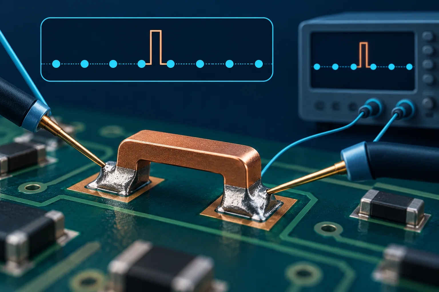
Consider ideal point readings every 100 μs, equivalent to 10 kS/s, at 0, 100 and 200 μs. An ideal 20 μs disturbance occurring only from 30 to 50 μs can lie completely between readings. This illustrates possible missed events; it is neither a jumper acceptance limit nor an instrument-selection formula.
NI's time-domain digitizer guidance considers sampling, bandwidth and interpolation together. Display refresh is not sample rate. Faster sampling alone does not remove front-end bandwidth, channel-switching or acquisition-dead-time limits.
| Item | Define | Avoid |
|---|---|---|
| Event | Threshold, polarity and minimum duration | Comparing differently defined counts |
| Acquisition | Sampling, bandwidth, minimum pulse and dead time | Using display rate alone |
| Decision logic | Filtering, debounce, latching and rearming | Treating suppressed events as absent |
| Circuit boundary | Excitation, sensing and parallel paths | A bypass masking the target open |
| Evidence | Timestamps, traces, counts and exposure periods | Post-test continuity alone |
Verify the complete detection channel
The glitch-detection discussion in the Tektronix TLA 700 manual illustrates dedicated detection of events between sample clocks. It describes a particular instrument, not every oscilloscope or logger.
Before exposure, competent personnel can validate the complete acquisition and alarm path using safe simulated signals with known width and amplitude, including near-threshold and consecutive events. Preserve configuration, stimulus and captured evidence. A software microsecond setting does not prove equivalent probe, front-end or storage performance.
Isolate power and identify the monitored path
This guide concerns isolated test coupons or approved low-energy monitoring, not live high-voltage busbar wiring. Test leads, fixtures and external connections can themselves create intermittent signals. A reference or empty-fixture channel can help investigate; do not assign every alarm to a jumper joint automatically.
For surface mount PCB jumper validation, supply schematics, test nodes and the environmental plan. See parallel paths in in-circuit measurements. Fast acquisition still requires a valid circuit boundary.
Questions
Do matching before-and-after readings prove no interruption? They do not establish every intervening instant; use an appropriate in-test method.
Do more alarms always mean worse joints? First check thresholds, repeat-count logic and fixture signals, then compare consistent methods.
The AI-generated cover contains conceptual traces and sampling dots, not measured Hongchuan data. No minimum interruption time, certification or instrument performance is claimed.