


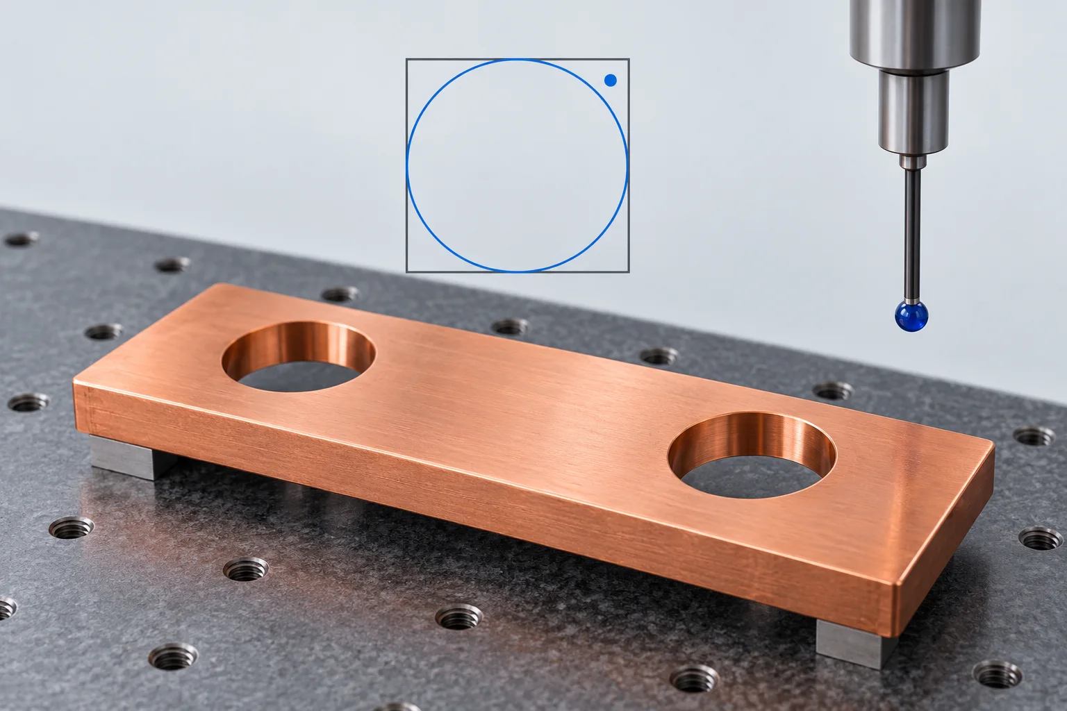
ΔX and ΔY in a PCB busbar inspection report are coordinate offsets. A position requirement with a diameter symbol needs evaluation against its specified zone. For a simplified 2D centre point, with a common datum alignment and no additional allowances, the diametrical deviation is 2√(ΔX²+ΔY²). Passing separate X/Y limits does not necessarily mean passing a circular zone.
Identify the specified region first
KEYENCE's location-tolerance guidance illustrates a circular diameter zone, and its measurement guide emphasizes evaluation relative to datums. Match the feature-control frame, datum references and theoretical location before reading the software result. Coordinates from different origins or alignments may not be directly comparable.
The example below concerns a centre point in one plane only. It excludes material-condition allowances, datum mobility, composite requirements and measurement uncertainty. A real hole's axis, depth and form still require evaluation under the complete drawing; one entrance centre is not a full axis inspection.
A square and a circle have different corners
Suppose X and Y are each allowed ±0.05 mm about their theoretical coordinates. Together they define a 0.10 mm square. A circular zone of diameter 0.10 mm has a radius of 0.05 mm. The square's corners lie outside that circle.
| Hypothetical ΔX, ΔY | Radial offset r | Diametrical value 2r |
|---|---|---|
| 0.03, 0.04 mm | 0.050 mm | 0.100 mm |
| 0.04, 0.04 mm | About 0.0566 mm | About 0.1131 mm |
Both coordinates in the second row satisfy ±0.05 mm, yet the centre is outside the example circle. The first row lies on its ideal boundary; actual acceptance still needs the agreed uncertainty and decision rule. These are geometric examples, not Hongchuan manufacturing tolerances.
Check whether the report already uses a diameter
Do not multiply a software result by two if it is already reported diametrically. Conversely, do not compare a radial distance directly with a diametrical limit. Preserve the field definitions, units, ΔX/ΔY and evaluation settings so the result can be reconstructed.
Hole form, tilt and centre changes with depth can affect full evaluation. The metrology owner should establish feature extraction, fitting and evaluation under the drawing's tolerancing system. Arbitrarily translating or rotating the alignment to centre a hole does not demonstrate conformance to the specified datums.
Make the RFQ reproducible
For custom PCB copper busbars, supply hole size, tolerance frame, datums, finished state and mating drawing. Record revision, hole ID, datum establishment, measurement depth, original coordinates and final reported quantity. “Hole position OK” is not a reproducible report.
The uncertainty and guard-band guide covers borderline decisions. Define the position zone first. This page neither converts position tolerance into assembly clearance nor authorizes hole enlargement or datum changes.
Questions
Can a diameter tolerance simply become half that value on X and Y? That changes the zone shape and needs design review, not an informal drawing substitution.
Is measuring only the hole entrance sufficient? Follow the controlled feature and complete drawing; one plane does not describe the entire axis.
Sources
KEYENCE location-tolerance explanation; KEYENCE position measurement relative to datums.
The AI cover illustrates hole-position geometry, not Hongchuan equipment or inspection results. The 2D example does not replace complete GD&T requirements or establish manufacturing capability.