


AOI acceptance for surface mount PCB jumpers starts with confirming which controlled features the camera can observe, then validating criteria for those features. Occlusion, reflections and program settings can produce false calls or escapes. A pass result does not independently establish every hidden interface, electrical capability or mechanical property.
Map visibility at both jumper ends
OMRON's multi-direction imaging paper describes shadows and secondary reflections from surrounding components, and the importance of criteria even when solder shape is reconstructed correctly. Its equipment results and improvement percentages are not detection-rate evidence for a different production line.
Using the actual board revision, identify both ends, side faces and hidden underside regions. Record nearby tall components, bridge geometry and spacing. For each feature, specify viewing direction, illumination and visible area. A visible outer fillet does not establish coverage beneath an obstruction.
| Question | Evidence needed | AOI limitation |
|---|---|---|
| Missing part or visible displacement | Actual images, coordinates and validated program | Correct outline does not establish interface integrity |
| Exposed feet and solder shape | Suitable views, lighting and approved criteria | Occlusion and reflection affect interpretation |
| Hidden underside | Applicable supplementary inspection | No optical information means no direct optical verdict |
| Voltage drop and mechanical function | Appropriate functional tests | Appearance alone cannot provide them |
Validate 3D capability for the actual assembly
Optical height measurement depends on the method, surface reflection and geometric access. “3D AOI” alone does not document inspection coverage. Check actual span, bridge height, neighbors and solder shapes against the qualified program. Camera resolution is not an overall joint-detection specification.
OMRON's CT inspection paper discusses X-ray inspection for visually inaccessible joints. Select X-ray, sectioning or other methods according to the controlled defect and project risk. Each supplementary method also needs a defined purpose and limitation.
Review false calls and escapes with confirmed samples
Retain samples whose condition has been confirmed independently, their images and program revisions. Record lighting and decision regions. Evaluate false calls on known acceptable samples and escapes on known unacceptable samples, with defect definitions and sample provenance. An intentionally created anomaly may not reproduce real defect morphology.
Reviewing only alarmed boards describes the alarm population, but cannot fully reveal defects among unalarmed boards. Include appropriate review of unalarmed samples. Do not loosen criteria simply to reduce alarm counts; validate changes within the approved scope.
Include neighboring geometry in sample review
When evaluating surface mount PCB jumpers, provide drawings and surrounding layout for placement, soldering and inspection review. Changes to bridge height, span or nearby tall components require renewed coverage assessment.
Zero-failure jumper sample interpretation explains why sample outcomes need limits. A successful program trial does not demonstrate zero defects in all products.
Common questions
Will more exposure reveal an obstructed joint? Exposure changes captured light; physical obstruction requires a viewing or inspection solution.
Does an AOI pass remove resistance checks? Follow the functional requirements and approved inspection plan; the evidence serves different purposes.
References
OMRON multi-direction imaging and inspection criteria; OMRON CT inspection of inaccessible joints.
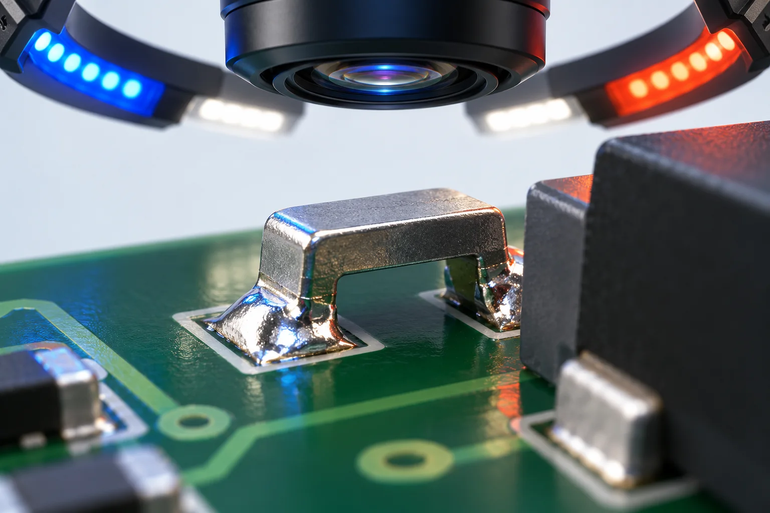
The cover is an AI optical-inspection concept, not Hongchuan equipment or test results. No detection rate, escape rate, zero-defect capability or current rating is claimed.