


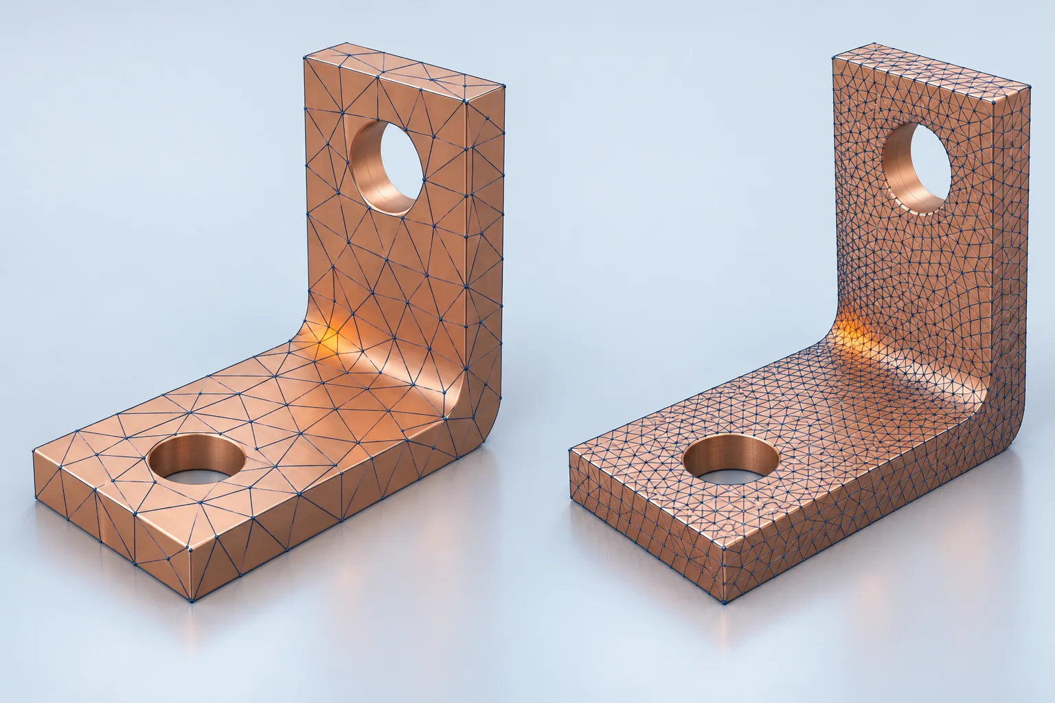
A red spot in PCB busbar FEA must be interpreted with geometry, loading and mesh changes. Ideal sharp corners, point loads or abrupt constraints can introduce stress singularities whose local peaks rise with refinement. Define fixed evaluation locations and output quantities, then compare meshes. A maximum-stress image alone does not establish failure or acceptance.
Locate the maximum in the physical assembly
COMSOL's singularity discussion shows a changing corner peak alongside a comparatively stable remote stress field. This describes mathematical behavior, not infinite stress measured in a real copper bar. Real fillets, contact edges and fatigue concerns still need assessment.
Check whether small fillets were removed, a bolt load was concentrated on one solid node, or a fixed boundary ends abruptly. Actual contact area, support stiffness and load introduction matter. Statements about point loads in solid models should not be transferred indiscriminately to beam or shell formulations.
Keep the evaluation location fixed
Choose the engineering output before refinement. A support-deflection question needs displacement at a defined location; a local-strength question needs a stress definition and material criterion. Solver convergence does not by itself demonstrate mesh adequacy.
| Review item | Retain | Misleading comparison |
|---|---|---|
| Mesh | Element formulation, order, local size in mm and quality | Only increasing the element count |
| Location | Fixed physical point, path or region | Moving several elements away each time |
| Output | MPa or mm and averaging settings | Mixing different reported quantities |
| Conditions | Material, loads, constraints and contact revision | Changing conditions while refining |
For a hypothetical fixed point, results of 80.0 MPa and 80.4 MPa differ by about 0.50% using the latter as denominator. This is only a comparison of two assumed values. Acceptance requires an agreed accuracy objective, further mesh evidence and a suitable model; 0.50% is not a universal criterion.
Plot smoothing does not resolve a singularity
Automatic color scales can make the same region appear different when a peak changes. Keep scales, units, locations and postprocessing settings consistent. Nodal averaging or smoother colors do not correct geometry or loading.
If local stress drives the decision, represent justified fillets, contact and distributed loading, then assess the relevant mesh. Crack or fatigue evaluations need their applicable methods and material data. Dividing a singular peak by material strength does not provide a useful general safety factor.
Make the report reviewable
For custom PCB copper busbars, submit drawing revision, board support, external loads and temperatures. Keep model simplifications, mesh comparisons and evaluation coordinates with the results.
Busbar hole position inspection addresses delivered geometry. Assess whether actual deviations change model assumptions; an ideal CAD calculation does not replace incoming inspection.
Common questions
Does a rising peak always mean increasing physical danger? First investigate its location and possible singularity, then assess the real local feature.
Do stable remote results approve the whole connection? They support only the corresponding output and region, not every contact or solder joint.
References
COMSOL stress singularities; COMSOL mesh refinement studies.
The cover is an AI mesh illustration with no actual stress scale. No Hongchuan simulation, strength rating, safety factor or simulation service capability is represented.