


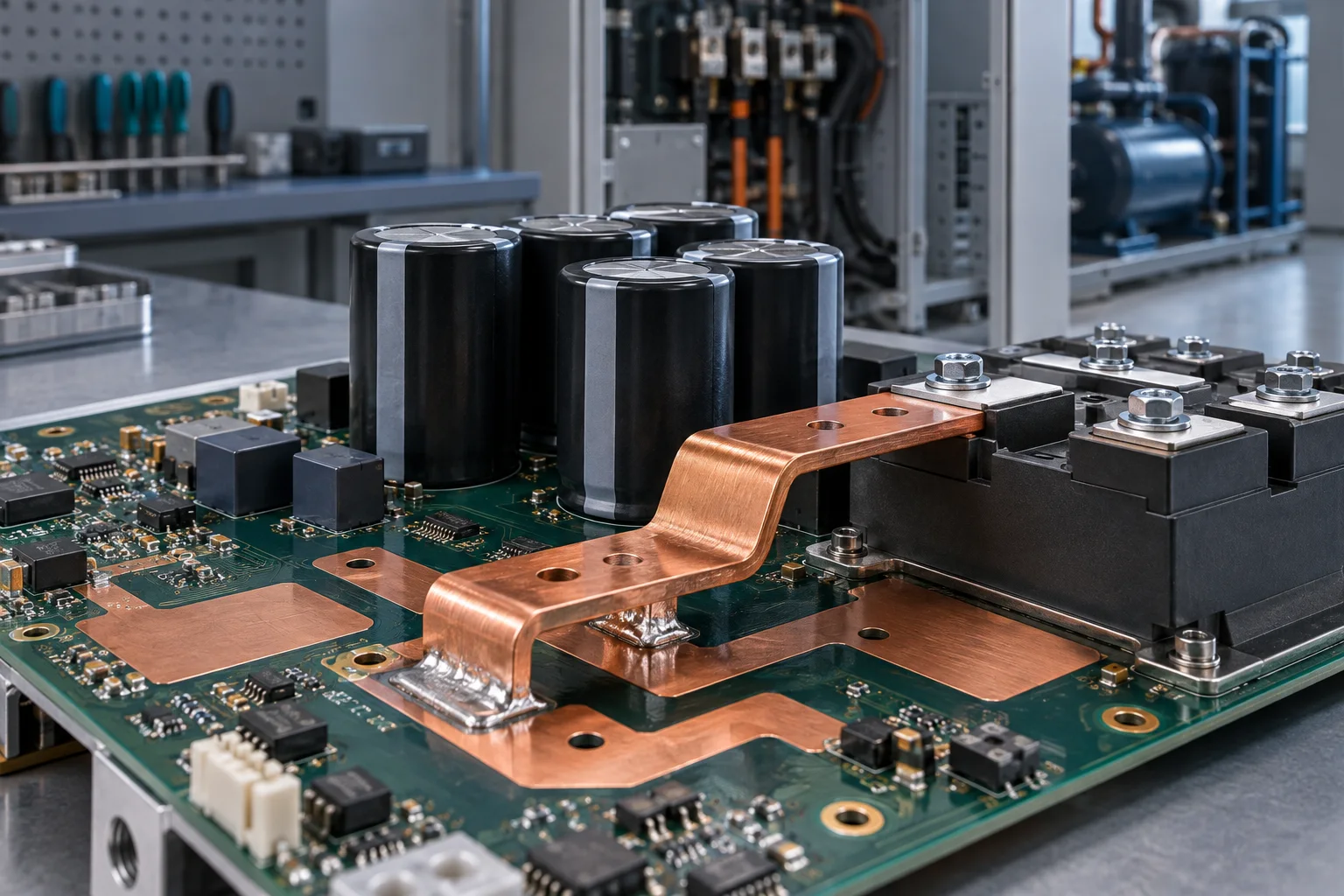
Quick answer: Do not size an SMD busbar for an industrial chiller compressor inverter from nameplate current alone. Validate start current, DC-link ripple, speed cycling, PCB pad exits, maximum cabinet temperature and worst-case airflow. Acceptance should combine segmented voltage drop, hot-spot temperature and reflow quality.
Questions answered
- Where does the busbar sit in a chiller inverter?
- How do start current and speed cycling affect selection?
- Why can the pad exit run hotter than the bar?
- Where should temperature be measured?
- Which reflow checks are required before production?
Application context
The power board connects rectification, DC-link capacitors and IGBT or SiC switching modules. An SMD busbar shortens the high-current path and supports automated assembly, but usable current still depends on copper, section, bends, finish, solder feet and the receiving PCB structure.
Selection inputs
| Input | Required data | Risk |
|---|---|---|
| Current | Continuous value, start peak, duration and cycles | Transient heat or drop |
| DC link | Voltage, ripple, switching frequency and loop position | Parasitics and local heat |
| PCB | Board and copper thickness, pads, layers and vias | Pad-exit hot spot |
| Environment | Inlet temperature, airflow, condensation boundary and nearby heat | Heat accumulation or insulation loss |
Temperature, drop and reflow validation
Test cold start, low-speed operation, rated load, maximum speed, repeated starts and maximum cabinet temperature. Use four-wire readings at the capacitor, bar, solder feet, pad exits and power module, with temperature at the same points. If the exit is hot, use this pad-exit troubleshooting guide. Validate stencil aperture, paste volume, coplanarity, board support and profile on the real assembly, then repeat resistance and temperature after thermal cycling.
FAQ
Is compressor nameplate current sufficient?
No. Include start peak and duration, ripple, airflow and the PCB exit structure.
Is a thicker bar always better?
No. Excess thermal mass can narrow the reflow window and increase stress, space and cost.
What belongs in an RFQ?
Provide voltage, current waveform, duty, board copper, pad drawing, airflow and temperature limit. Start with the SMD busbar page.