


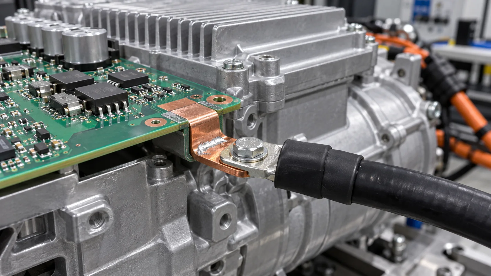
Quick answer: Review an EV electric-compressor inverter terminal across HV DC input, three-phase output, cable and housing mechanics. Measure terminal, solder, PCB copper and lug drops separately. Cable bending and compressor vibration should be carried by the housing or bracket, not by the PCB joint alone.
Questions answered on this page
- What makes an e-compressor inverter terminal different?
- How should HV input and three-phase output be selected?
- How should hole, pad, lug and bolt be matched?
- How should vibration and thermal cycling be checked?
- How can terminal, solder and lug heating be separated?
Application context
An EV electric compressor converts HV DC to three-phase motor current. The PCB terminal connects the power board to the external HV cable or motor interface near capacitors, power modules, aluminum housing and cooling hardware. Hongchuan supplies PCB welding terminals matched to voltage, current, PWM, cable, board, copper, hole, bolt and mounting direction.
Input and phase-output differences
| Position | Condition | Focus |
|---|---|---|
| HV DC input | DC, ripple and peak | Drop, insulation and capacitor loop |
| Three-phase output | PWM and motor load | Phase match, vibration and cooling |
| PCB joint | Thermal, board and process cycling | Fill, pad and support |
| External interface | Cable bend, fastening and sealing | Contact, torque and strain relief |
Match hole, pad, lug and cable support
Hole selection must satisfy leg insertion, solder fill, lug position, face overlap and HV spacing. The lug face should remain flat; washer and torque must match terminal thickness and material. Trace the main path, measure terminal, solder, copper and lug drops separately, and use the housing or clamp for cable bending. See terminal hole and pad design.
Temperature and reliability validation
Use ripple and peak on the HV input and real PWM loads for three-phase output, including continuous operation. Measure terminal body, solder, PCB exit, lug, housing and nearby devices under the real cooling condition. Thermal imaging finds hot spots; four-wire drop separates resistance. Run vibration, shock, thermal cycling and condensation-related inspection in the real orientation, then repeat resistance, phase drop and temperature. See terminal loosening after thermal cycling.
FAQ
Is the terminal rating enough?
No. Validate PCB joint, copper exit, lug contact, insulation spacing and post-vibration drift.
What if phase temperatures differ?
Compare phase current, path length, pads, contact and cooling boundaries using segmented drop.
How should samples be specified?
Provide HV current, PWM, cable, board, copper, hole, bolt and orientation. Use the high-current PCB hardware selection guide.