


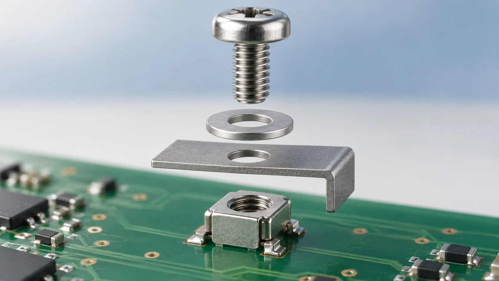
Direct answer A screw for an SMT nut must satisfy both minimum effective thread engagement and maximum permitted penetration. Thread designation or overall nut height alone is insufficient. A screw may engage too little, bottom in a blind hole or protrude into the PCB even when the specified tightening torque is observed.
Separate four dimensions
| Symbol | Definition | Check |
|---|---|---|
| L | Screw length from the chosen bearing datum to its end | Match the screw drawing's datum |
| T | Clamped stack from that datum to the nut entrance | Include bracket, washer and relevant steps |
| e=L−T | Geometric penetration | Not all of it is effective engagement |
| a | Equivalent loss from chamfers and incomplete end threads | Confirm from drawings or the supplier |
Confirm the length datum on the actual screw drawing; do not automatically include or subtract the head height. For a blind thread, distinguish usable screw-in depth, physical hole depth and full-thread depth. Würth's blind-hole terminal drawing and handling notes specifically address screw-in depth. Overall component height should not be substituted for it.
A tolerance example
This is a hypothetical geometric calculation. Let L=5.00±0.10 mm and T=2.00±0.15 mm. Minimum penetration is 4.90−2.15=2.75 mm; maximum penetration is 5.10−1.85=3.25 mm.
If the design separately requires 2.50 mm of effective engagement and the drawing establishes a maximum incomplete-thread allowance of 0.30 mm, worst-case effective engagement is only 2.45 mm. That fails the assumed requirement. If the supplier confirms a minimum usable screw-in depth of 3.50 mm, maximum penetration leaves 0.25 mm clearance. Whether that is adequate depends on the agreed anti-bottoming margin. None of these values is an HC-SP nut specification.
Add the missing assembly checks
For blind holes, check the screw end against the hole bottom. For through threads, check PCB clearance and any protrusion toward copper, components or the enclosure. A conductive screw near another potential also requires the equipment's electrical-clearance assessment; absence of mechanical contact is insufficient.
Record the complete screw part number, length tolerance, washer and bracket thicknesses, and soldered nut height. Trial the longest screw with the thinnest stack and the shortest screw with the thickest stack. Confirm actual clamping without bottoming before torque and reliability tests. A manufacturer's breaking torque is not a routine assembly setting.
Common questions
Is engagement equal to one screw diameter always enough? Material, thread tolerances, load and solder-joint capacity still matter. Use the specific drawing and validation requirements.
Can lower torque fix bottoming? Resolve the dimensional interference first, then establish the assembly torque.
Related products and reading
Explore related products · Torque-out versus tightening torque · Send drawings and application conditions
Sources
Sources checked on 6 October 2026. Worked examples explain methods, not HC-SP product ratings or test results. Cover is an AI-generated engineering illustration, not an actual product photograph.