


Select PCB solder terminals using an applicable current-temperature derating curve at the intended ambient temperature, with matching wiring, PCB, neighboring loads and cooling. Identify whether the curve is a base curve or already corrected permissible current. Do not mechanically apply the same correction twice.
Why a current number is incomplete
The public scope of IEC 60512-5-2:2002 covers current-carrying tests for electromechanical components, essentially connectors, at elevated ambient temperature. It provides no Hongchuan terminal rating or evidence of compliance. A value determined in one assembly cannot automatically be transferred to a hotter or more densely populated board.
| Check | Required context | Mismatch risk |
|---|---|---|
| Ambient temperature | Measurement location, airflow and stability | External air differs from air beside the terminal |
| Loaded neighbors | Number and arrangement energized | One contact differs from multiple heated contacts |
| Wiring and PCB | Wire area in mm², length, copper thickness and geometry | Changed heat and resistance paths |
| Limiting materials | Terminal, solder, PCB and insulation conditions | Metal melting point alone is irrelevant to assembly acceptance |
| Curve type | Base, corrected or assembly-validated | Missing or duplicated correction |
Where a 0.8 factor belongs
Phoenix Contact's connector test explanation distinguishes base and adjusted curves and describes a 0.8 correction for the stated method, accounting for tolerances and measurement uncertainty. That does not mean every Hongchuan terminal should simply be run at 80% of a nominal rating.
Hypothetically, if an applicable procedure requires 0.8 and the base curve gives 25 A at the target temperature, corrected current is 20 A. If the delivered curve already gives corrected current of 20 A, the same correction is not automatically applied again to obtain 16 A. Additional system margin needs its own documented basis. None of these values is a Hongchuan rating.
Evaluate a bare metal terminal as an assembly
No plastic housing does not mean unlimited capacity. For a PCB solder terminal, review the metal, solder transition, board copper, wiring and nearby materials. Another manufacturer's connector-housing temperature limit is not a limit for this assembly.
Agree current steps, ambient control, steady-state criteria, measurement locations and stop conditions. Retain original data from the actual board and wiring. Reassess coverage after changing adjacent loads, conductors or enclosure conditions. Do not extrapolate beyond validated temperature ranges or infer continuous current from a short cool-running trial.
Request comparable quotation data
Submit temperature range, continuous/pulsed load, wiring, board construction, adjacent loads and enclosure state. Ask for curve origin, correction, hotspot measurements and scope. Unconfirmed thread sizes are drawing requests, not verified saleable SKUs. See the terminal temperature-rise and resistance guide for measurement planning.
FAQ
Does larger copper establish a higher rating? No; verify the changed assembly.
Is one fixed temperature-rise limit sufficient? Identify the applicable specification and limiting materials first. Connector or rail-terminal limits are not universal for PCB solder terminals.
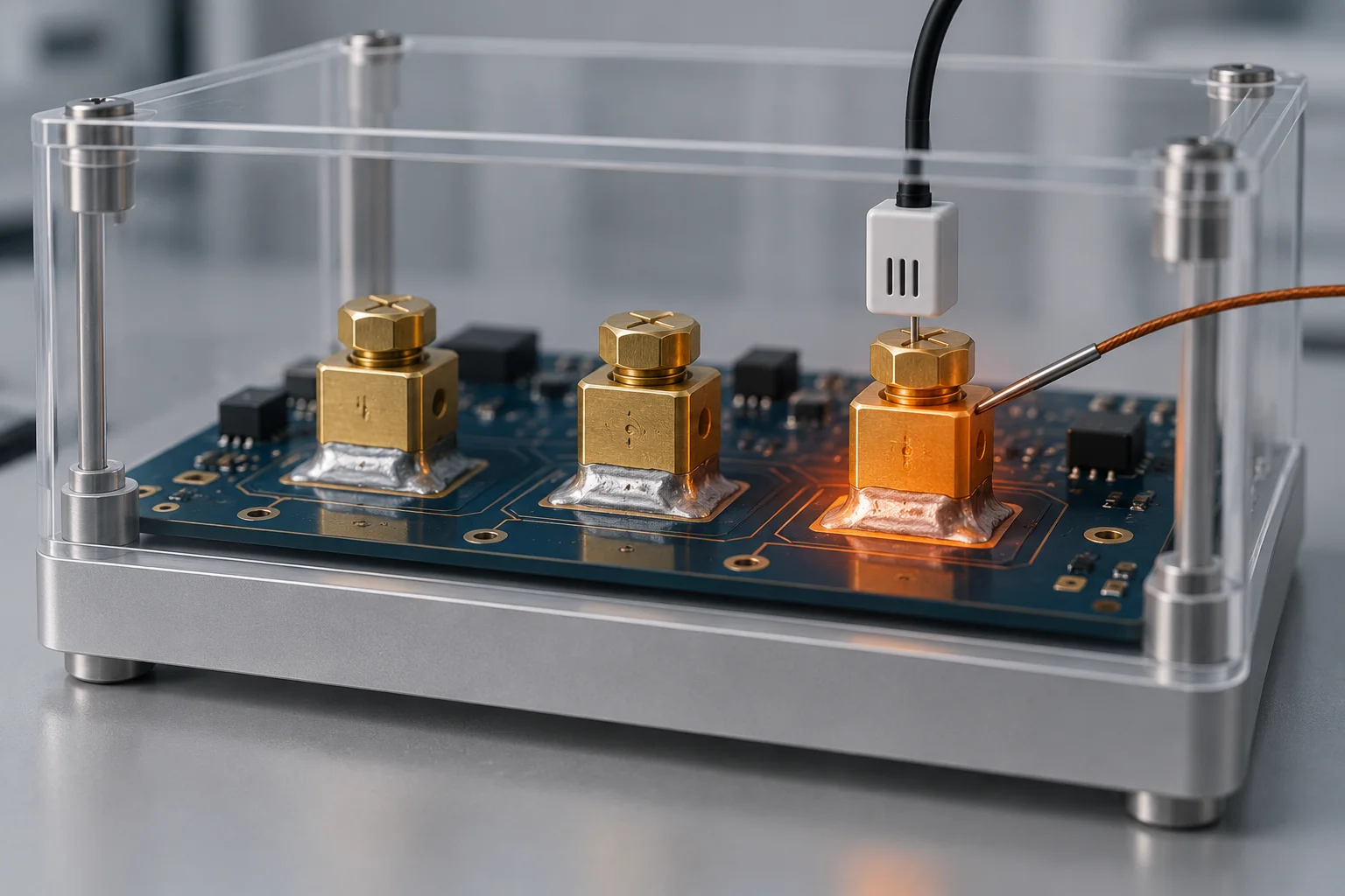
AI-generated thermal-test illustration, not Hongchuan test results. Current examples are hypothetical; no product current rating, certification or universal temperature limit is provided.