


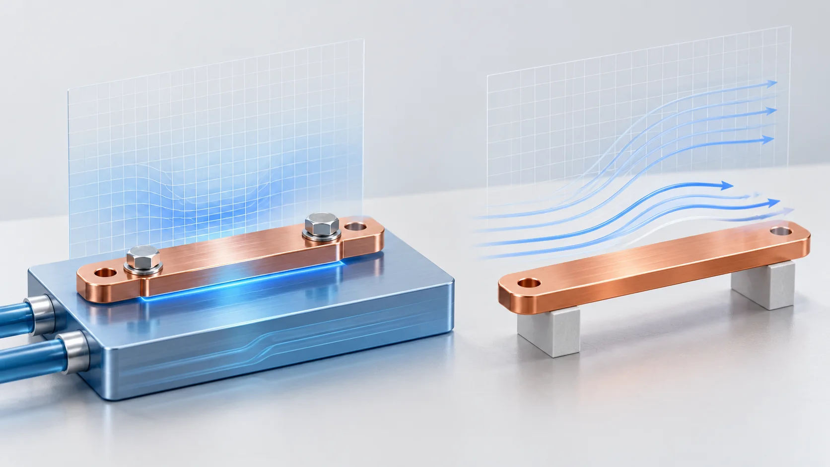
A PCB copper busbar surface fixed at 30 degrees C is physically different from a surface exchanging heat with air at 30 degrees C through convection. The first constrains surface temperature. The second defines heat flux through a temperature difference and a heat transfer coefficient. Review the physical boundary before comparing predicted temperatures.
Separate surface and fluid temperatures
COMSOL distinguishes specified-temperature and specified-heat-flux conditions. A common inward convective flux is q0=h(Text-T), with external fluid temperature Text and surface temperature T. Outward cooling uses the opposite sign. Keep the direction convention explicit.
| Boundary | Input | Physical justification |
|---|---|---|
| Specified temperature | Surface temperature in degrees C or K | How that region is maintained at the stated temperature |
| Convection | h in W/(square metre K), fluid temperature | Geometry and flow assumptions |
| Insulation | Zero normal heat flux | Why heat transfer through that face is neglected |
| Specified heat flux | W per square metre and selected region | Source, direction and distribution |
Calculate one face only
Assume area 0.002 square metres, uniform h=20 W/(square metre K), surface temperature 60 degrees C and air at 30 degrees C. Considering only convection from this face, Q=hA(T-Text)=1.2 W. The temperature difference is 30 K. The assumed h is not a general recommendation for natural or forced convection.
That example permits a 60-degree surface. Fixing the same surface at 30 degrees C instead constrains its temperature, with heat flow determined by the rest of the model. Identical numerical temperature entries do not make those boundary types interchangeable.
Do not substitute conductivity for h
Material conductivity k uses W/(metre K), whereas h uses W/(square metre K). COMSOL explains that the convective coefficient depends on fluid properties, geometry and flow. Surface coefficients and an explicit surrounding-fluid model are alternative modelling approaches requiring suitable assumptions.
For a PCB SMD busbar, identify whether a fixed-temperature region represents a cold plate, a board copper region or a measured location. Retain the basis and disclose omitted contact, solder-joint and PCB thermal paths. The cover cold plate is only a boundary concept.
Keep model versions comparable
A practical review record includes source power in W, selected faces, fluid temperature, coefficient basis, contact conditions and material versions. If cooling changes with geometry, the temperature difference cannot be attributed solely to busbar size. See installed airflow and fan operating points when relating a model to a real enclosure.
Questions
Is an unmarked face necessarily insulated? Inspect the chosen interface and settings rather than relying on displayed arrows.
Does fitting h to one temperature validate the model? Retain the fitting basis and check independent conditions; one point cannot validate every heat path.
Sources
COMSOL temperature and heat-flux boundaries;COMSOL convective heat transfer correlations
The cover is an AI thermal-boundary concept, not a measured field or Hongchuan test. The example establishes no cooling performance, current rating or simulation-service commitment.