


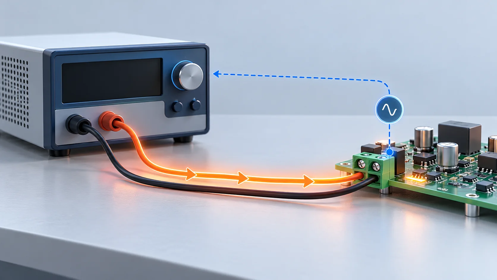
In a PCB solder terminal test, power-supply remote sense uses feedback from defined remote points to regulate voltage and compensate power-lead drop within the supply limits. Those points define the regulated location. Remote sense does not remove conductor resistance or heating; terminal voltage drop needs its own defined measurement points.
Identify where the voltage is regulated
NI explains that lead resistance reduces voltage at the load and that remote sense compensates using load-side feedback. TDK-Lambda describes output adjustment through that feedback and advises checking the model-specific compensation range. The same 24 V setting can therefore correspond to different voltages at the supply power terminals.
For an ideal steady DC example, assume actual current remains 10 A and the total resistance of both power leads is 0.10 ohm. Their combined drop is I times R, or 1.0 V, and their loss is I squared R, or 10 W. This assumed resistance belongs to the lead loop, not a measured Hongchuan terminal.
| Ideal condition | Supply power terminals | Load sense points | Lead loss |
|---|---|---|---|
| Local regulation at 24 V | 24 V | 23 V | 10 W |
| Remote regulation at 24 V load | About 25 V required | 24 V | Still 10 W |
The second row requires a supply that can maintain this operating point within compensation and protection limits. Current is assumed unchanged. The table does not calculate a new equilibrium for a constant-resistance or constant-power load, or imply that every nominal 24 V supply can deliver 25 V.
Measure the connection independently
If sense points are downstream of a terminal section, feedback may compensate its path drop while the load reading stays near the setpoint. The joint can still dissipate heat. For PCB solder terminals, retain actual current, independent terminal voltage points and temperature conditions. A stable load voltage alone cannot establish connection quality.
See four-wire terminal resistance and measurement boundaries for point definition. Label supply feedback and the separate voltage reading used for terminal resistance in the report. Do not attribute the entire cable-loop loss to one terminal.
Keep the operating limits with the results
TDK-Lambda advises checking compensation capability, output adjustment and overvoltage protection. Sense-lead fault behaviour also requires the specific equipment documentation. This article gives no universal wiring procedure; qualified test personnel should use the manual and approved procedure, including de-energizing before connection changes as required.
A useful report retains supply model and mode, sense-point sketch, voltage setting in V, actual current in A, supply-terminal and load voltages, and current-limit or protection status. Align sense locations before comparing samples. Startup dynamics or oscillation need separate measurements.
Questions
Does remote sense reduce terminal resistance? It changes supply regulation. Contact resistance remains a property of the actual connection and its condition.
Does a constant 24 V load reading clear the terminal? Check its independent drop, current and temperature; feedback may be compensating path losses.
Sources
NI remote-sense fundamentals;TDK-Lambda remote sense limits;TDK-Lambda remote sense and OVP.
The cover is an AI feedback concept, not an actual wiring diagram or Hongchuan test. Dashed paths illustrate feedback only. All numerical values are hypothetical and establish no terminal rating or supply capability.