


Direct answer Start with ΔL=αLΔT to estimate free expansion, then analyse restraint from supports and joints. The formula estimates how much a material would expand freely. It does not by itself predict interface stress, bolt-preload change or thermal-cycle life.
Calculate the difference for a stated example
Table 14 in CDA's architectural-applications publication lists reference linear-expansion coefficients of 16.9×10⁻⁶/K for C11000/C12200 copper and 22.2×10⁻⁶/K for aluminum. These values illustrate the calculation; replace them with appropriate alloy- and temperature-specific data for an actual design.
Assume two separate, freely expanding conductors, each initially 300 mm long, with a uniform 60 K temperature increase and approximately constant α.
| Material | Calculation | Free expansion |
|---|---|---|
| Copper | 16.9×10−6×300×60 | 0.3042 mm |
| Aluminum | 22.2×10−6×300×60 | 0.3996 mm |
| Difference | 0.3996−0.3042 | 0.0954 mm |
A 60 K temperature difference equals a 60 °C increase. At 600 mm, with all other assumptions unchanged, the difference becomes 0.1908 mm. If copper and aluminum have different lengths or temperature rises, calculate αAlLAlΔTAl and αCuLCuΔTCu separately.
Movement is not a completed joint design
Materials bonded together do not behave like two independent free strips. Interface restraint, supports, joint stiffness, cross-sections, elasticity and possible plastic deformation affect loading. Copper for Busbars also treats longitudinal expansion and differential expansion involving bolt materials as distinct joint-design concerns.
Consequently, 0.0954 mm is not automatically a slot allowance, and it does not justify increasing bolt torque. Contact pressure, insulation and maintenance constraints also apply. Where movement compensation is needed, mechanical and electrical designers must agree where it occurs and whether motion is permitted at the contact interface.
Prepare the review inputs
Identify actual copper and aluminum grades and tempers, interface construction, reference temperature and temperature distribution. Give effective lengths in mm and temperatures in °C. Mark fixed supports, compliant or sliding locations, assembly tolerances and permitted movement directions. Include bolt and washer details, preload requirements and adjacent-part clearances.
For a proposed thermal-cycle test, agree temperature limits, dwell times and cycle count. Define before-and-after checks for contact resistance, appearance and dimensions. These are test-planning inputs, not a claim that a particular joint has passed.
Common questions
Does a small expansion difference rule out loosening? No. Free-movement arithmetic excludes contact behaviour, relaxation and assembly stiffness.
Does an all-copper design eliminate expansion checks? Copper still expands, and supports or fasteners may use other materials. Review the complete assembly.
Related products and reading
Explore related products · Interface delamination and peel-strength evaluation · Send drawings and application conditions
Sources
- Copper Development Association, Architectural Applications, Table 14
- Copper for Busbars, sections 6.4 and 6.6.5
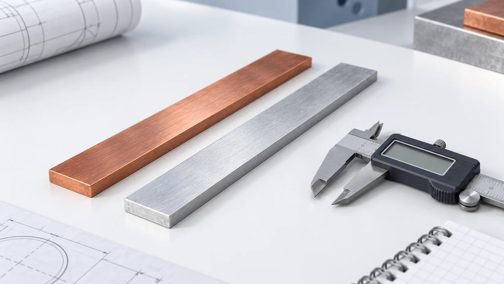
Sources checked on 6 October 2026. Worked examples explain methods, not HC-SP product ratings or test results. Cover is an AI-generated engineering illustration, not an actual product photograph.