


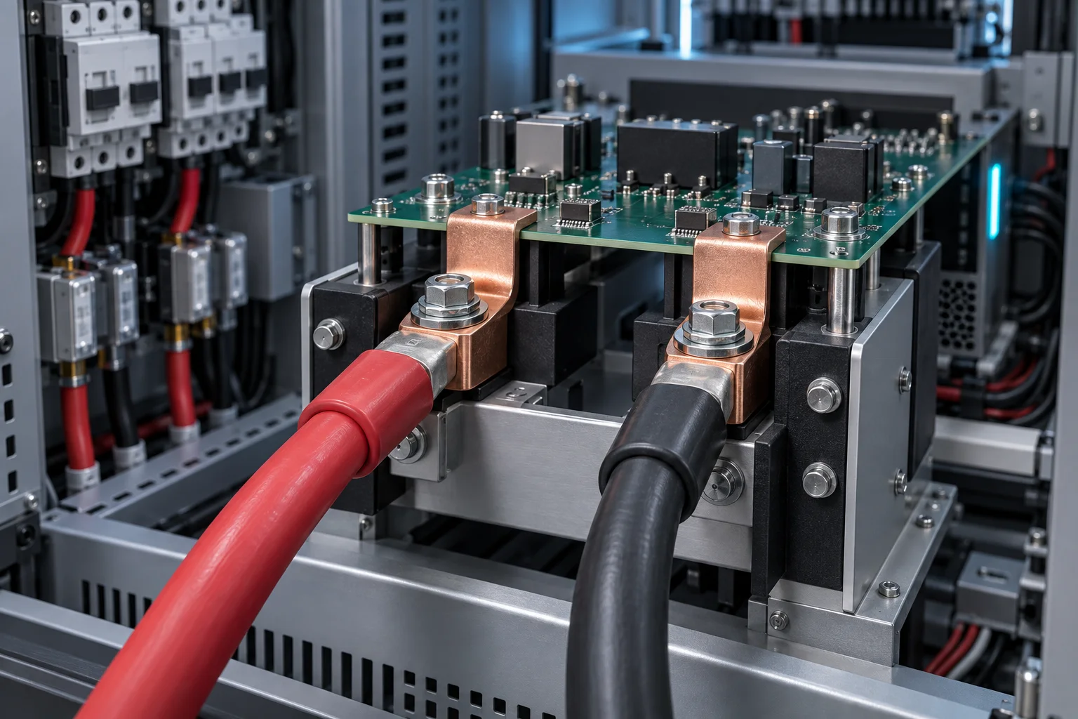
Quick answer: Select PCB welding terminals for a DC microgrid protection unit by separating continuous current from short fault current before interruption. Validate the terminal, pad exit, positive-to-return spacing, cable support and contactor shock together. A component current rating does not replace system fault-energy and insulation-coordination tests.
Questions answered
- Which current data does a protection terminal need?
- Is short fault current the same as continuous ampacity?
- How are DC creepage and clearance confirmed?
- How are cable and bus loads kept off the PCB?
- What is repeated after a protection event?
Application context
A DC microgrid protection unit connects sources, storage, feeders, contactors, fuses or solid-state switches. A PCB welding terminal provides a board interface, but short-circuit withstand depends on fault magnitude, clearing time, loop inductance and heat distribution and must be confirmed at system level.
Design inputs
| Item | Required data | Validation |
|---|---|---|
| Normal operation | Continuous/peak, bidirectional power and maximum ambient | Drop and steady temperature |
| Fault process | Prospective current, I²t, clearing time and reclose | Deformation, erosion and insulation |
| Insulation | Voltage, pollution, altitude and coating boundary | Creepage and clearance |
| Mechanical | Cable, termination, clamp, torque and vibration | Solder fatigue |
Validation sequence
Establish low-resistance and temperature baselines at the terminal, solder leg, pad exit and cable end. Cover one-way, bidirectional, peak and maximum-temperature operation, then perform controlled fault-and-clear tests defined by the protection scheme. Inspect discoloration, erosion, looseness, cracks and insulation, and repeat resistance. If heat is concentrated at the PCB exit, follow this overheating guide.
FAQ
Does surviving one fault prove the design?
Not necessarily. Confirm clearing time, repeatability, post-test insulation and serviceability.
Can conformal coating replace creepage distance?
Not directly; validate material, process, pollution and applicable standards.
What belongs in an RFQ?
Provide voltage, waveform, fault I²t, clearing time, board copper, cable and environment. Start with the welding terminal page.