


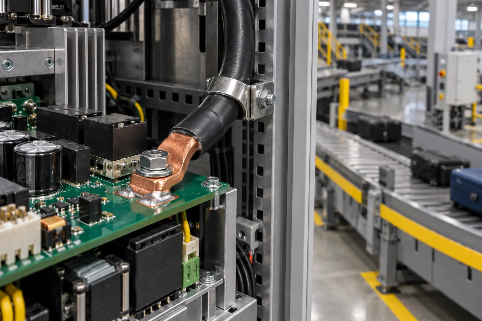
Quick answer: Select PCB welding terminals for an airport baggage conveyor VFD by validating frequent starts, belt-jam current, staged motor operation, cable mass and service handling together. Rated current is only a screen; the pad exit, cable clamp and post-vibration resistance govern long-term reliability.
Questions answered
- Where are high-current terminals used in conveyor VFDs?
- How do jam and restart events affect peak current?
- Why does a heavy cable need independent support?
- What should be repeated after vibration and service?
- How is terminal heat separated from PCB heat?
Application and boundaries
Baggage systems contain many motors, branch cabinets and drives. A PCB welding terminal may connect rectifier input, DC link or motor output, but its solder joint should not carry cable mass, door movement or maintenance pull.
| Boundary | Review | Risk |
|---|---|---|
| Electrical | Continuous, start/jam peak, harmonics and allowed drop | Excess temperature |
| Mechanical | Cable, bend radius, clamp and vibration | Solder fatigue |
| Manufacturing | Hole, pad, fill and verticality | Poor joint or offset |
| Service | Removal count, tool access and reassembly | Over-torque or cable damage |
Validation sequence
Record initial four-wire resistance, solder fill and cable support. Run cold start, rated load, simulated jam and short-interval restart. Measure terminal body, solder leg, pad exit, via field and cable crimp. Repeat the same points after vibration, thermal cycling and service removal. If the PCB exit is hotter than the terminal, follow this terminal overheating guide.
FAQ
Can motor rated current size the terminal?
Not alone; include jam, restart, ambient temperature and drive output characteristics.
Is a PCB-mounted cable tie enough?
Usually not. Clamp heavy cables to the cabinet or a dedicated support.
What belongs in an RFQ?
Provide waveform, cable, board copper, pad, vibration, airflow and service conditions. Start with the welding terminal page.