


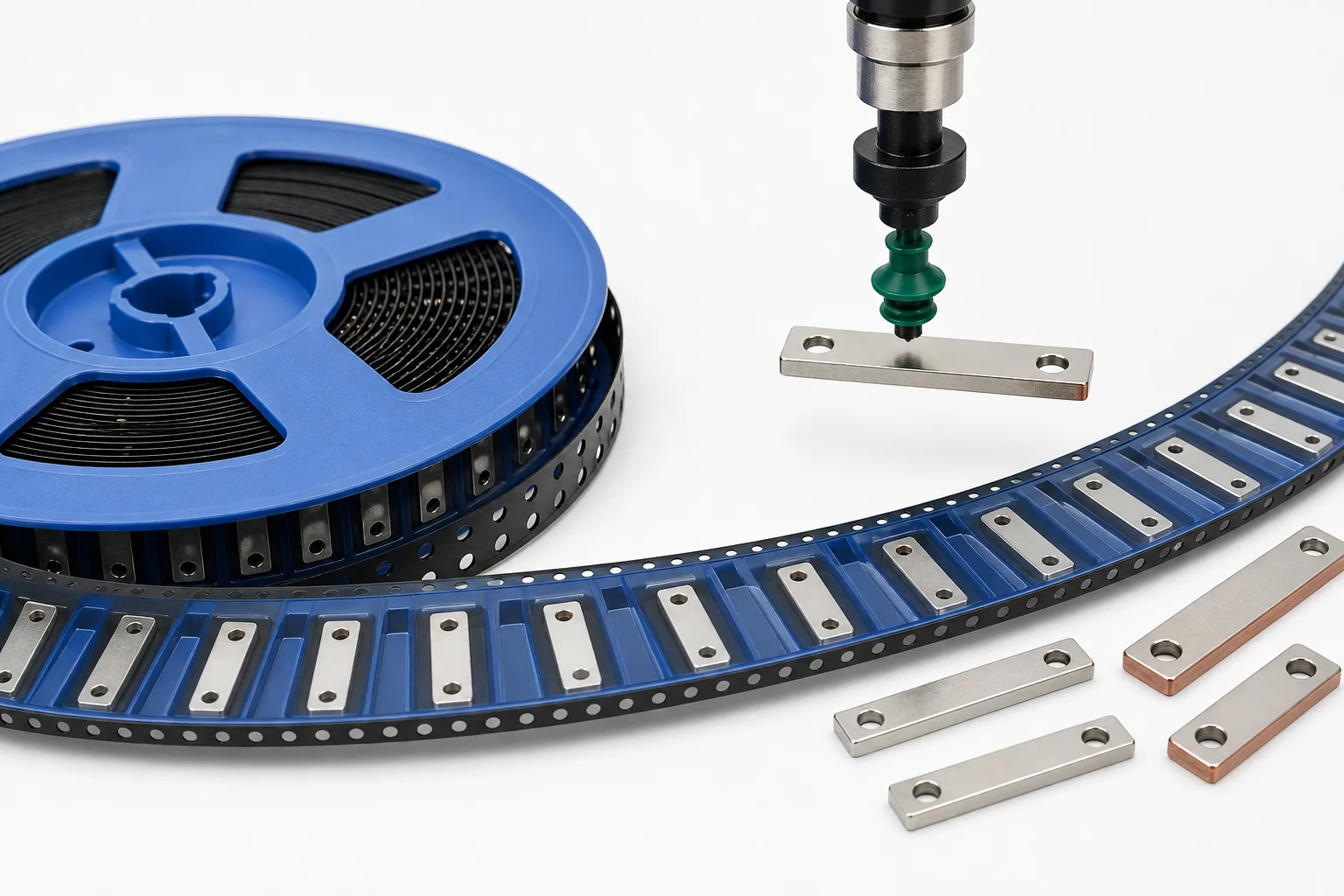
Quick answer: Reliable SMT placement of SMD copper busbars depends on tape-and-reel packaging, not only part dimensions. The carrier pocket must prevent rotation and bouncing, the nozzle pickup surface must be flat, and tape orientation must match the PCB pad direction and placement program.
Questions answered on this page
- What tape-and-reel dimensions matter for SMD copper busbars?
- Why does the nozzle pickup surface affect SMT yield?
- What happens when tape orientation and PCB pad direction do not match?
- How should packaging poka-yoke be verified before mass production?
Engineering summary
- The carrier pocket must do more than fit the part; it must control rotation, lift and forward/backward movement during feeder vibration.
- The pickup surface should be flat, centered and free from burrs or plating bumps.
- Tape orientation must be confirmed against PCB pad direction, placement coordinates and post-reflow inspection needs.
- Validation should use the real feeder, real nozzle and real placement speed.
Why packaging controls placement stability
SMD copper busbars are heavier and longer than many standard SMT parts. If the tape pocket is too loose, the part can rotate during feeding. If it is too tight, pickup can fail. A shifted busbar reduces effective solder-pad contact area and can cause uneven solder fillets, local heating or virtual solder joints.
Packaging should therefore be reviewed together with part geometry, plating, nozzle selection and PCB pad design. Standard options can be checked in the SMD busbar product category.
Tape-and-reel checklist
| Item | Check | Failure mode |
|---|---|---|
| Pocket width | Side clearance and rotation control | Placement angle error |
| Pocket depth | Part sits below cover tape but does not jam | Pickup failure |
| Nozzle pickup face | Flat, centered, no burrs | Drop, skew, mispick |
| Tape orientation | Matches PCB coordinates | Reverse placement |
| Cover-tape peel force | Stable peel without lifting parts | Jumping or missing parts |
Pre-production validation
- Confirm orientation. Put first-part tape direction, PCB pad direction and placement angle in one review drawing.
- Run feeder pickup tests. Record mispicks, drops, flips and jams over 200-500 placements.
- Inspect after reflow. Check solder wetting, coplanarity, end fillets and shift.
- Measure temperature rise. Test the busbar, pad exit and adjacent copper area on a powered sample.
FAQ
Do SMD copper busbars always need tape-and-reel packaging?
For automated SMT placement, tape-and-reel is usually the most efficient and repeatable option.
Can any flat face be used for nozzle pickup?
No. The pickup surface should be flat, centered and away from holes, bends, burrs or plating irregularities.
Who decides tape orientation?
PCB design, SMT process and supplier teams should confirm it together. Supplier default orientation may not match the placement program.