


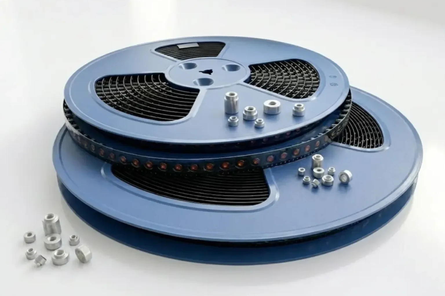
Quick answer: SMT nut pad design for reflow soldering should be selected from the real current path, allowed temperature rise, soldering process window, board stack-up, and mechanical fixing method. For inverter control boards and compact power modules, the safest choice is usually not the largest metal part, but the part whose footprint, plating, packaging and inspection method match the assembly line.
Required inputs before selection
Before choosing SMT nut, prepare five inputs: continuous current, peak current duration, PCB copper thickness, soldering process, and mechanical load. These values decide whether the design should use a standard SMD busbar, a PCB welding terminal, an SMT nut, or a custom stamped connector.
If the project is still in early layout, compare this article with the high-current PCB hardware selection guide and the full SMT nut product category. Those pages help connect the article advice to actual standard parts, drawings and quotation discussions.
Selection table
| Decision point | What to check | Why it affects reliability |
|---|---|---|
| Current path | Peak current, continuous current and parallel paths | Prevents local heating and uneven current sharing |
| Metal geometry | Width, thickness, bend radius and contact area | Controls resistance, heat capacity and solder fillet shape |
| Surface finish | Tin, nickel, silver or custom plating requirement | Affects solderability, oxidation resistance and contact stability |
| Assembly process | Reflow, wave soldering, selective soldering or manual process | Determines pad design, stencil opening and thermal balance |
| Mechanical load | Screw torque, cable pull, vibration and thermal cycling | Reduces cracking, loosening and fatigue around the solder joint |
Recommended engineering workflow
- Start from the current map. Mark where current enters, splits and returns. Do not size SMT nut only from total system current.
- Estimate temperature rise. Use the PCB copper area, copper thickness, airflow and nearby heat sources as part of the decision, not as an afterthought.
- Match the soldering process. A part that looks strong in CAD can fail production if its thermal mass is too high for the paste, stencil and reflow profile.
- Define inspection criteria. Agree on solder fillet visibility, coplanarity, plating appearance and packaging orientation before mass production.
- Validate with samples. Check contact resistance, pull force, torque behavior and thermal cycling before freezing the drawing.
Common mistakes
- Using board copper width as the only current-carrying criterion.
- Ignoring the difference between short peak current and continuous current.
- Choosing a custom part when a standard SMD busbar or terminal can reduce tooling risk.
- Forgetting tape-and-reel orientation or feeder compatibility during sourcing.
- Specifying plating without considering storage time and soldering atmosphere.
Checklist before requesting a quote
- Target current and allowed temperature rise are written on the drawing or RFQ.
- PCB pad dimensions, copper thickness and solder mask opening are available.
- Assembly process and reflow profile range are known.
- Mechanical load, screw size or cable direction is described.
- Packaging requirement is clear: bulk, tray, tube, tape and reel, or custom.
FAQ
Can a larger SMT nut always reduce temperature rise?
Not always. Larger metal can lower resistance, but it can also make soldering harder and shift heat into nearby components. The footprint and process window must be checked together.
Should I choose standard or custom metal parts?
Use standard parts first when the current, footprint and mounting method fit. Custom parts make sense when the current path, mechanical interface or packaging requirement cannot be solved by standard sizes.
What information helps suppliers respond faster?
Provide drawings, current level, PCB thickness, copper thickness, soldering process, plating preference, annual volume and packaging method.
How does Huichuan Metals support this selection?
Huichuan Metals can review the current path, recommend standard SMD busbars, welding terminals or SMT nuts, and provide manufacturable metal hardware options for high-current PCB projects.