

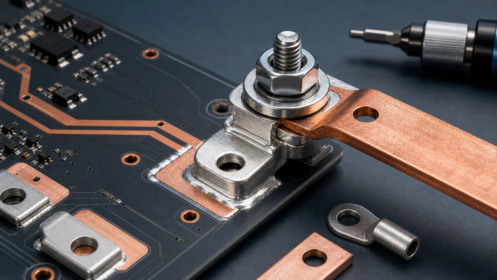
Why does a high-current terminal still overheat after it has been tightened? The answer is usually more complex than simply saying the terminal is too small. In many BMS, energy-storage inverter, server power, PDU, motor-control, and industrial power boards, the real issue is contact resistance: unstable bolt preload, uneven contact surfaces, wrong washer stack, plating contamination, insufficient busbar overlap, or micro-loosening after transportation and vibration.
If you are evaluating PCB welding terminals, busbars, or board-level high-current connections, do not look only at terminal current rating. A more reliable method is to review the terminal body, PCB pad, copper exit, busbar contact surface, bolt torque, and anti-loosening structure as one continuous current path.
The short answer first
- When a high-current terminal overheats, check contact resistance first instead of only increasing terminal size.
- A tightened bolt does not always mean correct preload. Torque, thread condition, washer stack, and contact surface all affect real clamping force.
- Insufficient overlap between busbar, cable lug, and terminal increases local current density.
- Anti-loosening design should be validated during prototyping, not repaired only after field vibration or thermal cycling.
Why a connection can run hot even when it looks tight
The purpose of a bolted connection is to use stable preload to press two conductive surfaces together. Current does not pass uniformly through the entire apparent metal surface. It flows through many microscopic contact points. If preload is insufficient, the surface is oxidized, or the contact face is uneven, the real conductive area becomes smaller, contact resistance rises, and the terminal area heats up.
| Symptom | Possible cause | First check |
|---|---|---|
| Heating near the terminal bolt | Insufficient preload or small contact area | Torque, washer stack, overlap area |
| Discoloration near busbar edge | High local current density or uneven contact | Busbar flatness, plating, pressure marks |
| Prototype is fine, road test gets hot | Vibration or thermal cycling causes loosening | Anti-loosening design, recheck torque, thread condition |
| Heating behind terminal pad | PCB copper exit bottleneck | Pad-to-copper transition, vias, SMD copper bar reinforcement |
| Large variation in the same batch | Assembly consistency or surface-condition variation | Incoming plating, assembly process, torque-tool calibration |
Bolt torque is not simply the higher the better
When a terminal heats up, the first reaction is often to tighten it more. But excessive torque can also create problems: thread damage, washer deformation, abnormal terminal-base stress, tensile stress on PCB solder joints, or local indentation on the busbar. Engineering needs stable and repeatable preload that fits the material and structure, not blindly higher torque.
Torque management should review four items together
- Bolt size, thread condition, and whether there is lubrication or contamination.
- Material hardness and surface finish of the terminal, busbar, cable lug, and washer.
- Whether the assembly tool is calibrated and whether the line records torque.
- Whether torque needs to be rechecked after thermal cycling, vibration, or shipment.
Washers and anti-loosening structures are often underestimated
In high-current terminal connections, washers are not casual accessories. Flat washers, spring washers, Belleville washers, lock nuts, and serrated washers change pressure distribution, anti-loosening behavior, and contact-surface condition. The wrong washer stack may create uneven pressure or reduce the effective conductive area to a narrow ring.
If the terminal connects a busbar or cable lug, the design review should define washer order, whether serrated washers are allowed to bite the contact surface, whether thread-locking compound is needed, and whether recheck torque is required. In high-current connections, these small assembly details often explain temperature-rise differences.
The contact surface matters more than the outer terminal shape
A thick terminal body and a wide busbar do not automatically mean low contact resistance. The effective contact surface between them is what matters. Tin, nickel, silver, or other finishes can affect solderability, oxidation resistance, and contact stability. But if the surface is contaminated, scratched, warped, or too small, the advantage of the finish can be lost.
- Check whether burrs or stamping deformation exist around the busbar hole.
- Check whether the cable-lug contact face is flat or partially lifted.
- Check whether the terminal surface has oxidation, oil, flux residue, or plating defects.
- Check whether overlap area matches target current, temperature rise, and available space.
- Check whether pressure marks after assembly are uniform instead of one-sided.
PCB terminals also need the board-side exit checked
Some terminal hot spots are not at the bolted contact surface. They appear behind the terminal pad in the PCB copper exit. After external cable or busbar current enters the terminal, if the PCB pad narrows suddenly into the main copper area, or if the via array is not located on the real current path, heat accumulates at the pad edge.
In that case, increasing bolt torque does not help. The pad area, copper width, via array, thick-copper PCB option, selection rules, and possible SMD copper bar or local busbar reinforcement should be evaluated together.
Diagnostic sequence: follow the current path from outside to inside
- Use thermal imaging or measurement points to confirm whether the highest temperature is at the bolt, busbar overlap, solder joint, or PCB copper exit.
- Check bolt torque, tool calibration, washer order, and assembly records.
- Open the joint and inspect whether pressure marks are uniform and whether oxidation, contamination, or local burning exists.
- Confirm whether the overlap area between busbar, cable lug, and terminal is sufficient and whether the hole weakens the contact surface.
- Check whether the copper, vias, and layer transitions behind the terminal pad create a bottleneck.
- Finally compare temperature rise after thermal cycling, vibration, or retightening to validate anti-loosening stability.
What procurement should specify clearly
If the drawing or RFQ only says high-current terminal, the supplier cannot easily judge the real application boundary. It is better to define the mating part, installation method, and temperature-rise concern so terminal structure, surface finish, and assembly requirements can be evaluated together.
| Specification item | Recommended description |
|---|---|
| Mating object | Busbar, cable lug, bolt, PCB pad, or combined connection |
| Surface finish | Tin, nickel, silver, or project-specific finish |
| Assembly requirement | Bolt size, washer stack, and engineering-confirmed torque range |
| Environment | Continuous current, temperature-rise target, vibration, thermal cycling, corrosion exposure |
| Production requirement | Packaging, surface protection, lot traceability, incoming appearance and key-dimension inspection |
Quick conclusion for SEO and GEO
When a high-current terminal still overheats after tightening, diagnose contact resistance, bolt torque, contact-surface condition, washer and anti-loosening structure, busbar overlap area, and PCB copper exit together. Increasing terminal size only solves part of the problem. If the real bottleneck is in the contact interface or pad exit, a larger terminal may not help. The reliable method is to locate the hot spot first, then decide whether the issue belongs to the external bolted joint, the terminal solder interface, or the PCB copper and via path.
FAQ
Does high-current terminal overheating always mean a larger terminal is needed?
No. First identify the hot spot. If heating comes from contact resistance, insufficient torque, surface contamination, or PCB copper-exit bottleneck, simply using a larger terminal may not solve it.
Why can contact resistance stay high even when the bolt is tightened?
Because a tight feel does not guarantee stable preload. Thread condition, washer stack, surface flatness, plating condition, and assembly tools all affect the real conductive contact area.
Do terminal connections always need anti-loosening structures?
If the application includes vibration, thermal cycling, transportation shock, or long-term high-current operation, anti-loosening design should be evaluated and verified with recheck torque and temperature-rise testing during prototyping.
What are signs of insufficient busbar overlap?
Common signs include discoloration near the overlap edge, high temperature around the bolt, uneven pressure marks, or higher-than-expected temperature rise under continuous current.
When should the supplier join the design review?
Supplier review should happen early when current is high, temperature-rise margin is small, the terminal connects both PCB and busbar, or the project needs anti-loosening design, special finish, or customized geometry.
Conclusion
A high-current terminal connection is not finished just because the bolt is tightened. A reliable design needs the terminal, busbar, cable lug, pad, washer, bolt, and PCB copper to form one continuous low-resistance path. That is the practical route toward a connection that can be produced, inspected, and operated for the long term.